For 1990-2009 cars only
Drive Pinion Flange/Yoke and/or Oil Seal Replacement RPOLP1/LY7
Special Tools
| • | J 42851 Seal Installer |
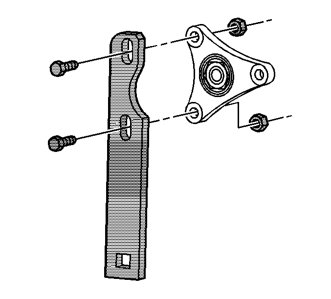
| • | J 45012 Holding Fixture |
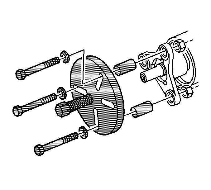
| • | J 45019 Flange and Pinion Cage Remover |
| • | J 34826 Hub Nut Socket (36 mm) |
Removal Procedure
- Raise and support vehicle. Refer to Lifting and Jacking the Vehicle.
- Remove the exhaust system. Refer to Exhaust System Replacement.
- Remove the propeller shaft. Refer to Rear Propeller Shaft Replacement.
- Use the J 45012 to hold the pinion flange.
- Using the J 34826 , remove the drive pinion nut.
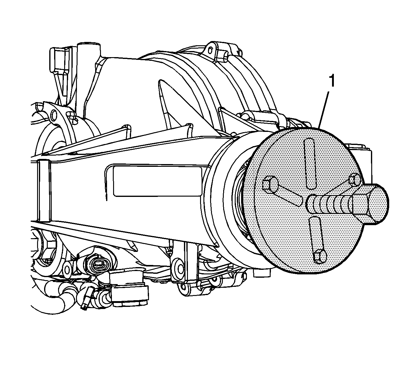
- Using the J 45019 , remove the flange.
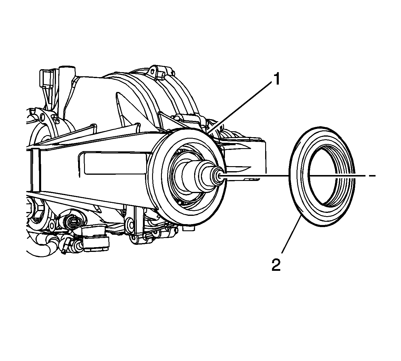
- Using a flat-bladed tool, remove the drive pinion seal. Take care not to damage any sealing surfaces.
Installation Procedure
- Apply a small amount of synthetic gear oil GM P/N 12378514 (Canadian P/N 88901045) or equivalent to the drive pinion flange sealing surface of the drive pinion seal.
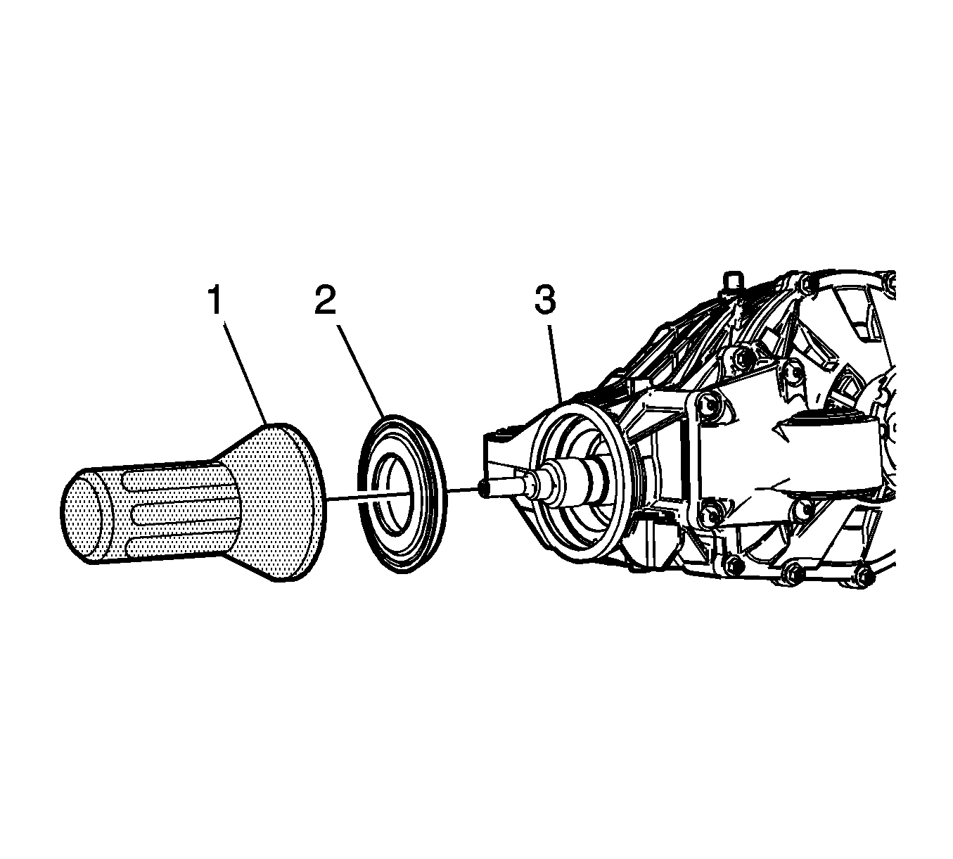
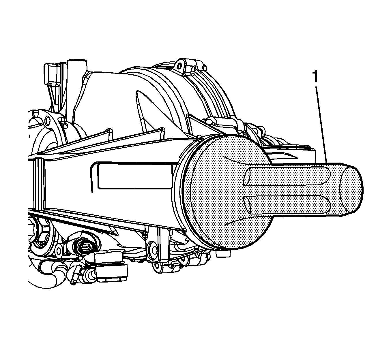
- Using the J 42851 (1), install the pinion seal (2) to the differential housing (3).
- Install the J 45012 on the drive pinion shaft.
- Install the pinion flange on the drive pinion shaft.
- Thoroughly clean the residue from the pinion shaft threads and the pinion flange nut by using denatured alcohol or equivalent and allow to dry.
- Apply threadlocker GM P/N 12345382 (Canadian P/N 10953489), or equivalent to 2/3 of the threaded length of the pinion shaft threads. Ensure that there are no gaps in the threadlocker along the length of the filled area of the pinion shaft threads.
- Allow the threadlocker to cure approximately 10 minutes before installation.
- Use the J 45012 to hold the pinion flange.
- Using the J 34826 , tighten the drive pinion nut to 245 N·m (181 lb ft).
- Install the propeller shaft. Refer to Rear Propeller Shaft Replacement.
- Inspect the fluid level. Refer to Rear Axle Lubricant Level Inspection.
- Install the exhaust system. Refer to Exhaust System Replacement.
- Lower the vehicle.
Note: Ensure the pinion bore is free of dirt debris.

Note: The pinion shaft threads and the pinion flange nut must be free of residue and debris prior to the application of the threadlocker.
Caution: Refer to Fastener Caution in the Preface section.
Drive Pinion Flange/Yoke and/or Oil Seal Replacement RPO LSA
Special Tools
| • | J 34826 Hub Nut Socket 36 mm |
| • | J 42851 Front Cover Oil Seal Installer |
| • | J 45012 Pinion Flange Holder |
| • | J 45019 Pinion Cartridge Remover |
Removal Procedure
- Raise and support the vehicle. Refer to Lifting and Jacking the Vehicle .
- Remove the exhaust system. Refer to Exhaust System Replacement .
- Remove the propeller shaft from the vehicle. Refer to Rear Propeller Shaft Replacement.
- Using the J 45012 holder (1) and the J 34826 socket (2), remove the drive pinion flange nut.
- Remove the J 45012 holder .
- Using the J 45019 remover (1), remove the flange.
- Using the appropriate tool, remove the drive pinion seal (2) from the differential housing (1).
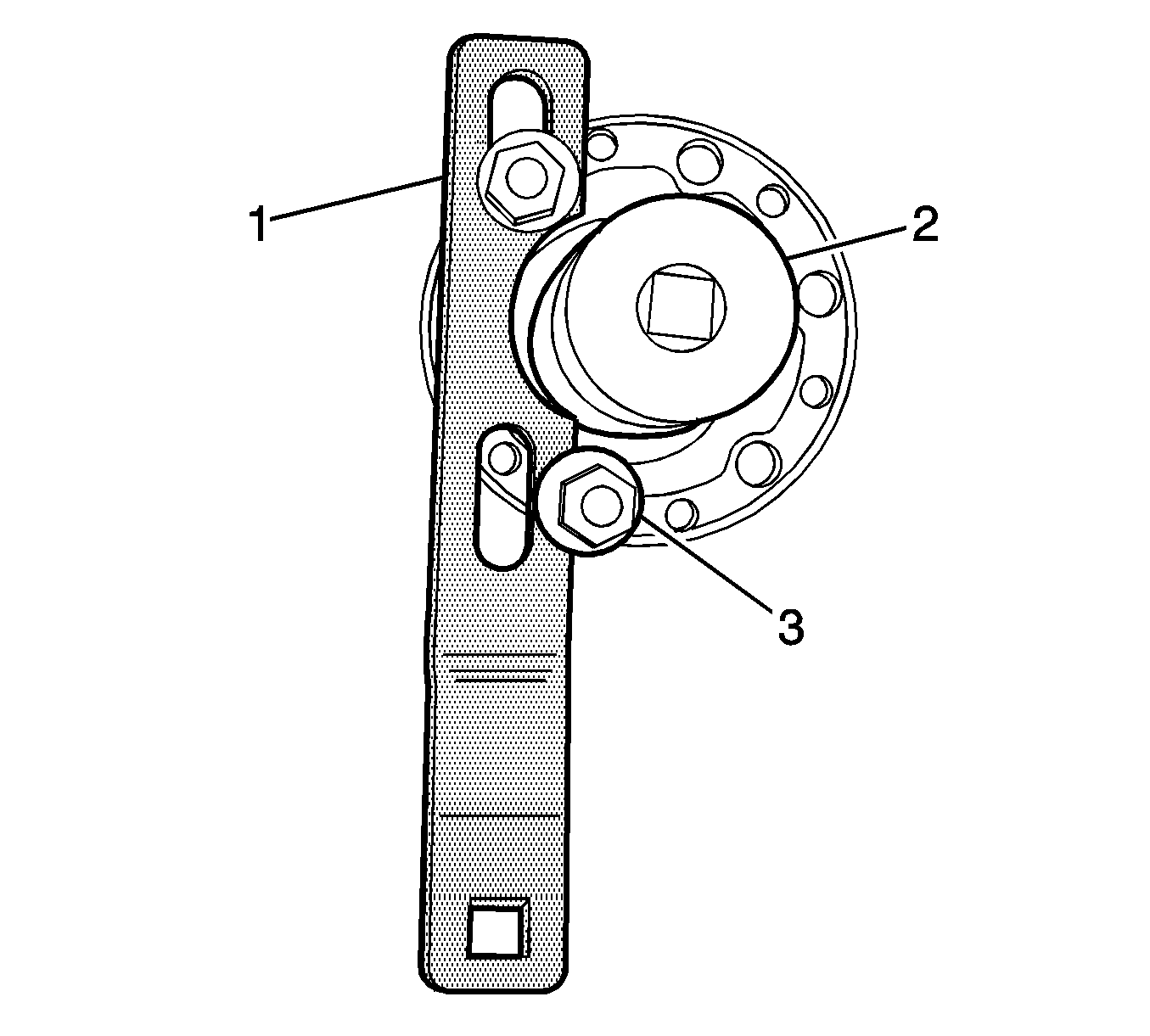
Note: Position the bolt (3) behind and outside of the J 45012.
Note: Do not damage the sealing surfaces of the pinion shaft or differential pinion housing.
Installation Procedure
- Remove any debris and excess gear lubricant from the pinion bore.
- Lubricate the drive pinion flange sealing surface with the gear lubricant. Refer to Adhesives, Fluids, Lubricants, and Sealers.
- Using the J 42851 installer (1), install the drive pinion seal to the differential housing.
- Using the appropriate cleaning solvent, thoroughly clean the drive pinion shaft threads and the drive pinion flange nut.
- Apply threadlocker to 2/3 of the threaded length of the pinion shaft threads. Refer to Adhesives, Fluids, Lubricants, and Sealers.
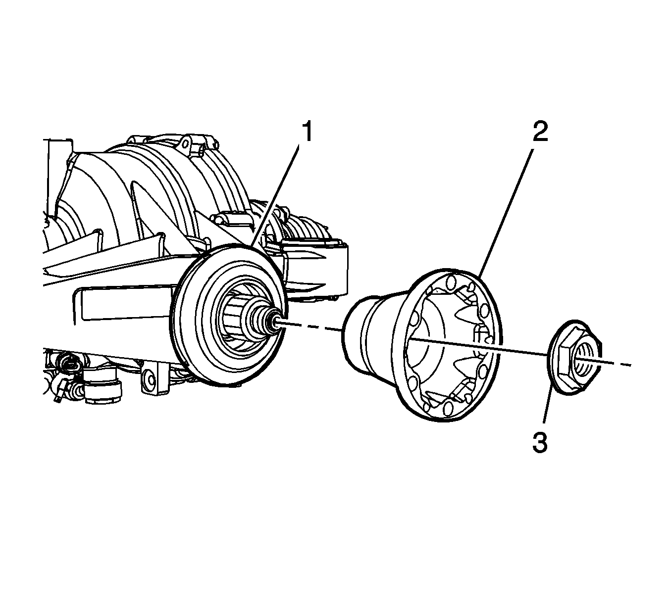
- Position the drive flange (2) on the pinion gear (1).
- Install the pinion nut (3) on the pinion gear (1).
- Using the J 45012 holder (1) and the J 34826 socket (2) , tighten the pinion nut to 245 N·m (181 lb ft).
- Install the propeller shaft. Refer to Rear Propeller Shaft Replacement
- Inspect the rear drive axle lubricant level. Refer to Rear Axle Lubricant Level Inspection .
- Install the exhaust system. Refer to Exhaust System Replacement .
- Remove the supports and lower the vehicle.
Note: Allow the drive pinion gear threads and the nut to air dry.
Note: Ensure that there are no gaps in the threadlocker along the length of the filled area of the pinion shaft threads.
Caution: Refer to Fastener Caution in the Preface section.

Note: Position the bolt (3) behind and outside of the J 45012.
