Special Tools
J 45859 Hub Puller .
Removal Procedure
- Raise and support the vehicle. Refer to Lifting and Jacking the Vehicle.
- Remove the tire and wheel assembly. Refer to Tire and Wheel Removal and Installation.
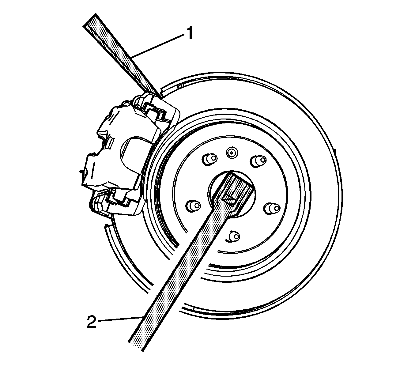
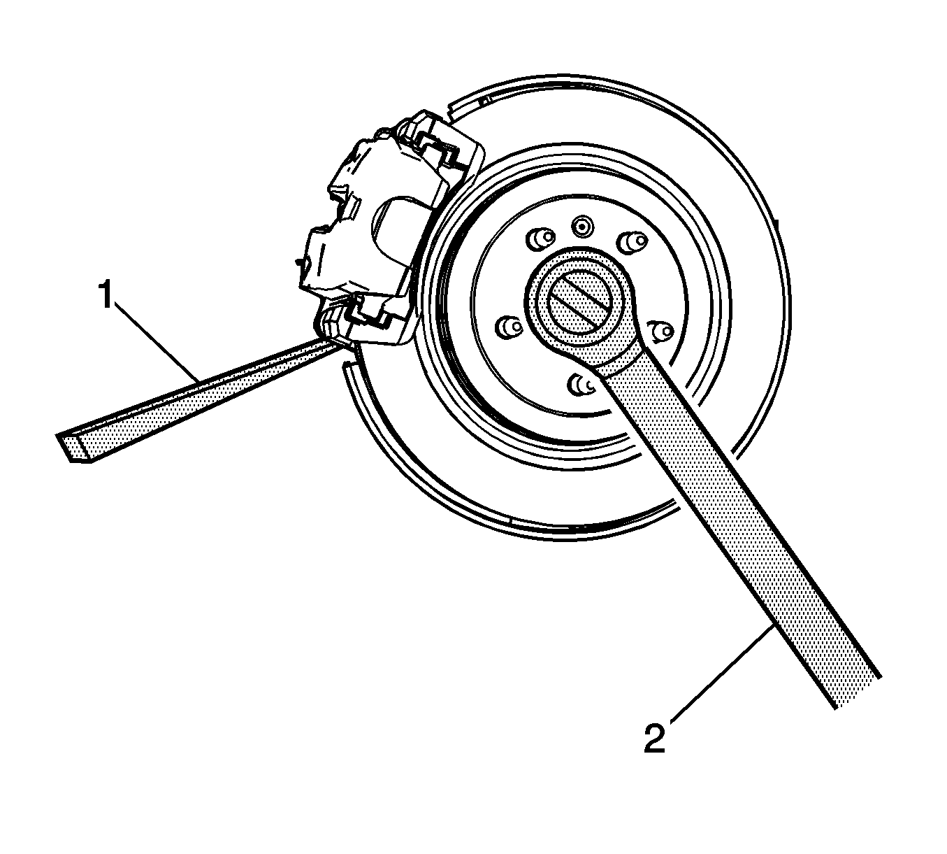
- Insert a drift or punch (1) in the brake rotor and against the brake caliper bracket.
- Using a breaker bar (2) and the proper size socket, loosen the wheel drive shaft retaining nut.
- Remove the wheel drive shaft retaining nut (1).
- Using the J 45859 puller , separate the wheel drive shaft from the wheel bearing/hub assembly.
- Remove the lower control arm. Refer to Lower Control Arm Replacement.
- Support the knuckle assembly with a jack stand.
- Mark the relationship of the wheel drive shaft to the output shaft flange.
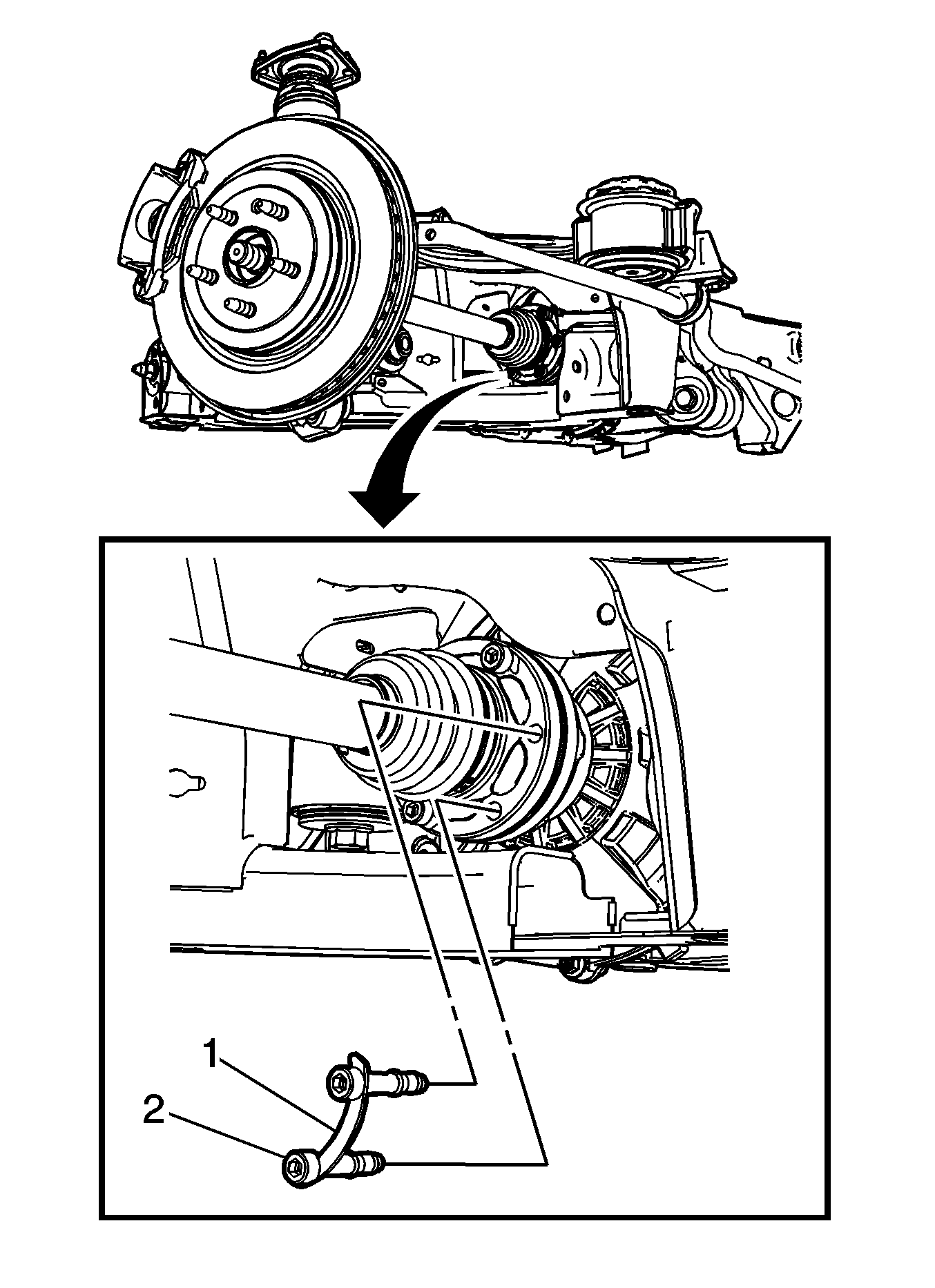
- Remove the wheel drive shaft mounting bolts (2) and the spacer (1) from the differential drive flange.
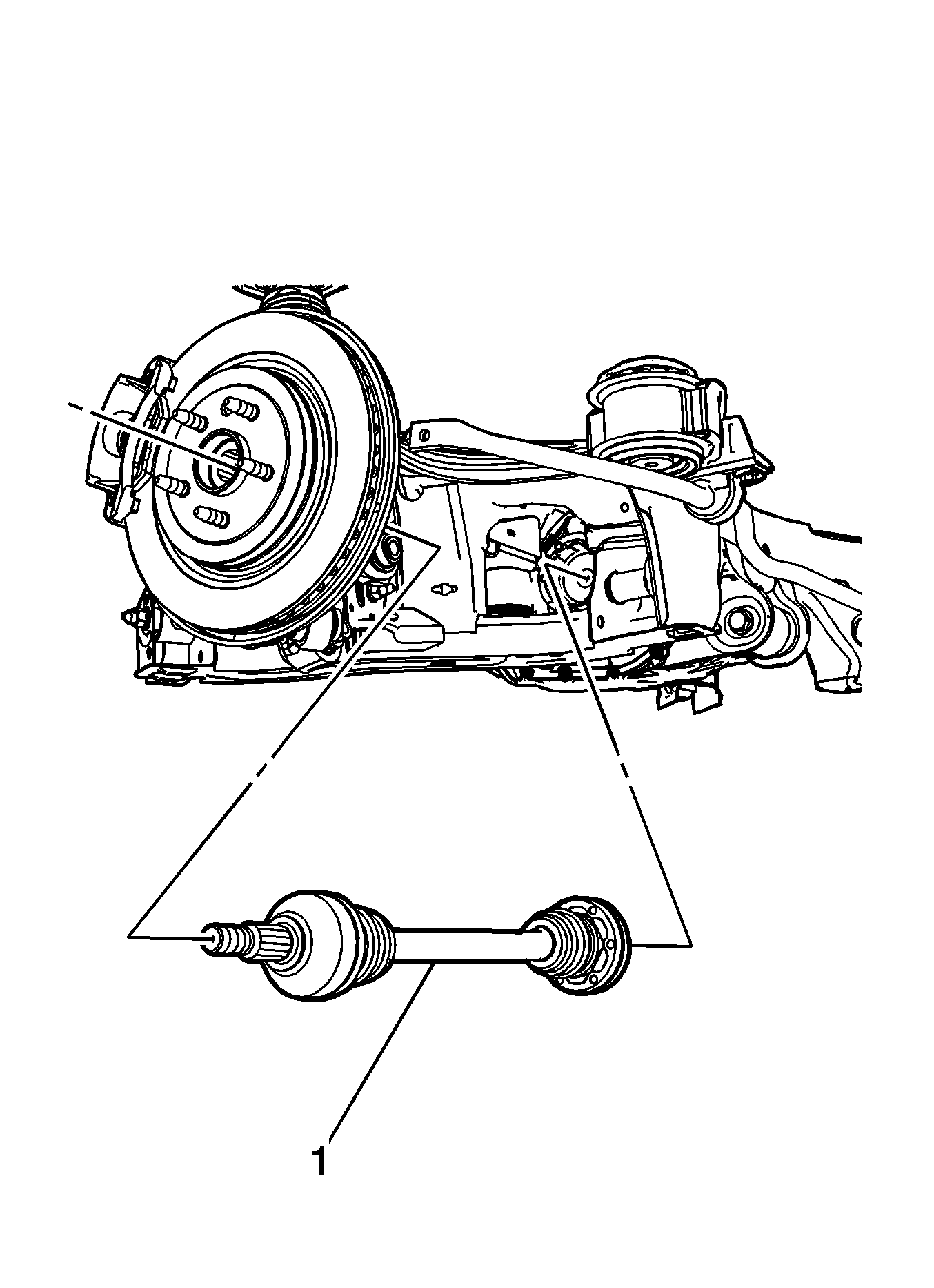
- Remove the wheel drive shaft (1) from the knuckle and support the drive shaft.
- Remove the wheel drive shaft (1) from the vehicle.
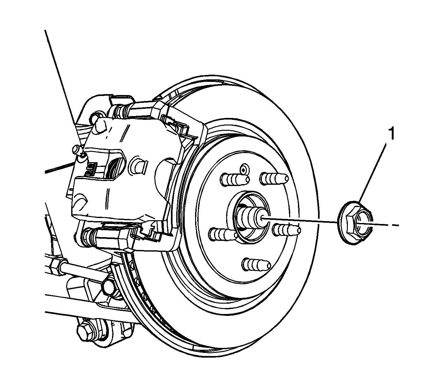
Note: DO NOT reuse wheel drive shaft retaining nut. Discard and replace with new.
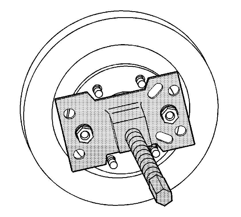
Note: Leave the J 45859 on the brake rotor, it will aide in the lifting and positioning the knuckle assembly on the jack stand.
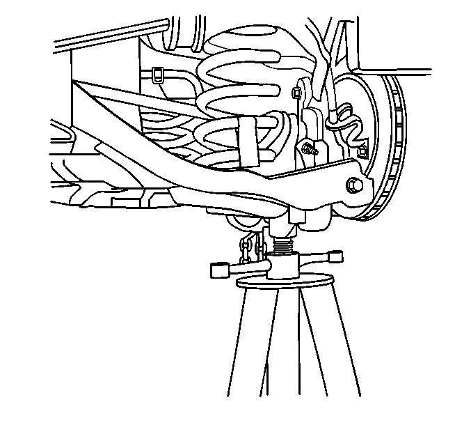
Note: Position the knuckle assembly to the side to have enough access area to remove the wheel drive shaft.
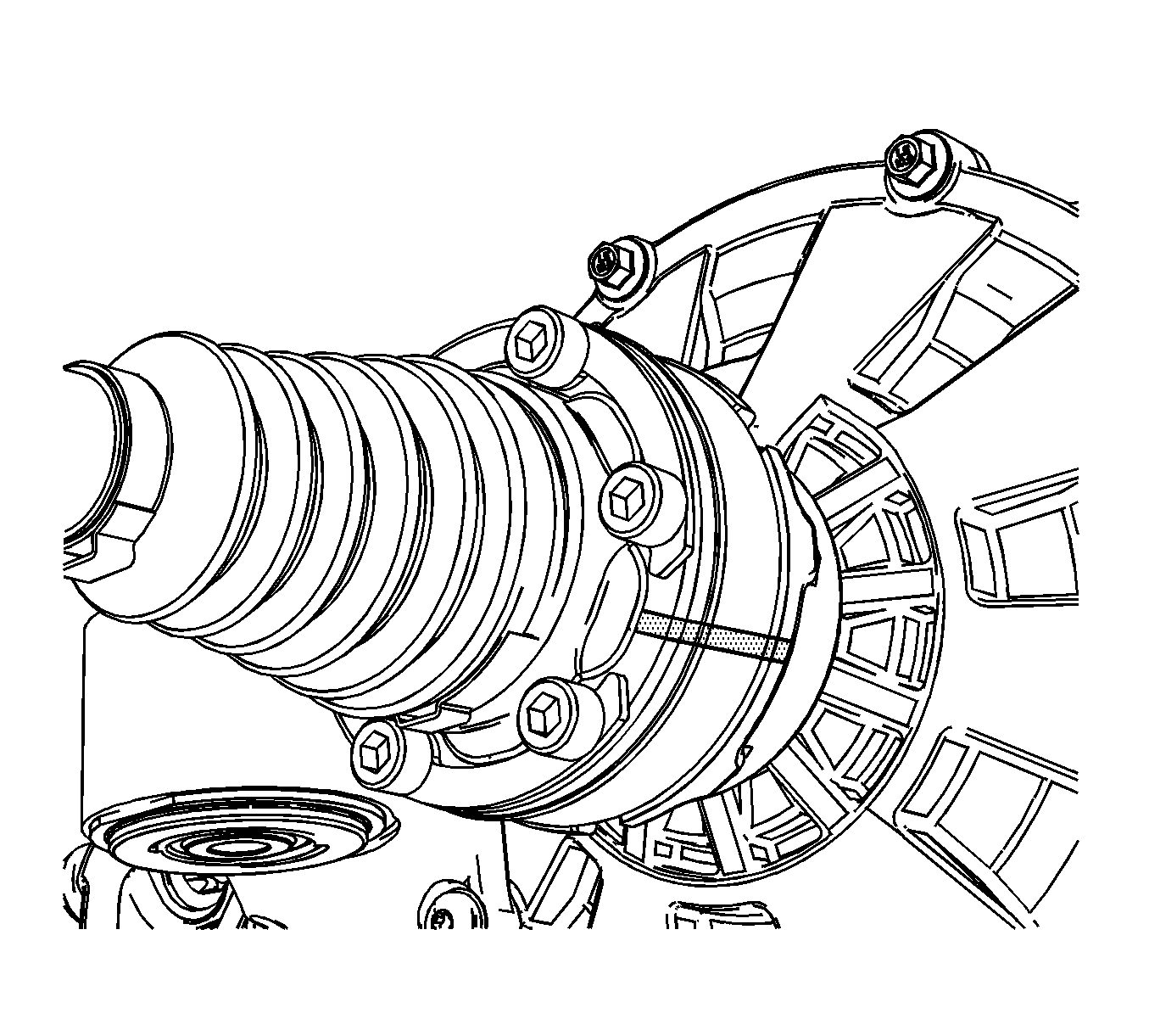
Note: It maybe necessary to use a flat bladed screw drive to separate the wheel drive shaft from the differential flange.
Installation Procedure
- Remove knuckle assembly from the jack stand.
- Remove the J 45859 from the brake rotor.
- Install the wheel drive shaft (1) in the knuckle assembly.
- Align the reference marks on the wheel drive shaft and the output shaft flange.
- Thoroughly clean the threads using denatured alcohol or equivalent and allow to dry.
- Apply threadlocker GM P/N 12345493 (Canadian P/N 10953488), or equivalent to the wheel drive shaft bolts.
- Install the mounting bolts (2) and spacer (1) on the differential drive flange and tighten to 50 N·m (37 lb ft).
- Install the wheel drive shaft nut (1).
- Insert a drift or a punch (1) in the brake against the brake caliper bracket.
- Using a torque wrench (2), tighten the wheel drive shaft nut to 215 N·m (158 lb ft)..
- Remove the drift or punch (1) from the brake rotor.
- Install the lower control arm assembly. Refer to.
- Install the tire and wheel assembly. Refer to Tire and Wheel Removal and Installation.
- Remove the support and lower the vehicle.

Note: If reusing the wheel drive shaft bolts, the threads must be free of debris prior to the application of the threadlocker to ensure the proper adhesion and retention.
Note: Ensure that there are no gaps in the threadlocker along the length of the filled area of the bolt. Allow the threadlocker to cure approximately 10 minutes before installation of the bolts.
Caution: Refer to Fastener Caution in the Preface section.


Note: Tighten the wheel drive shaft nut slowly to draw the wheel drive shaft into the knuckle prior to torquing to specifications
