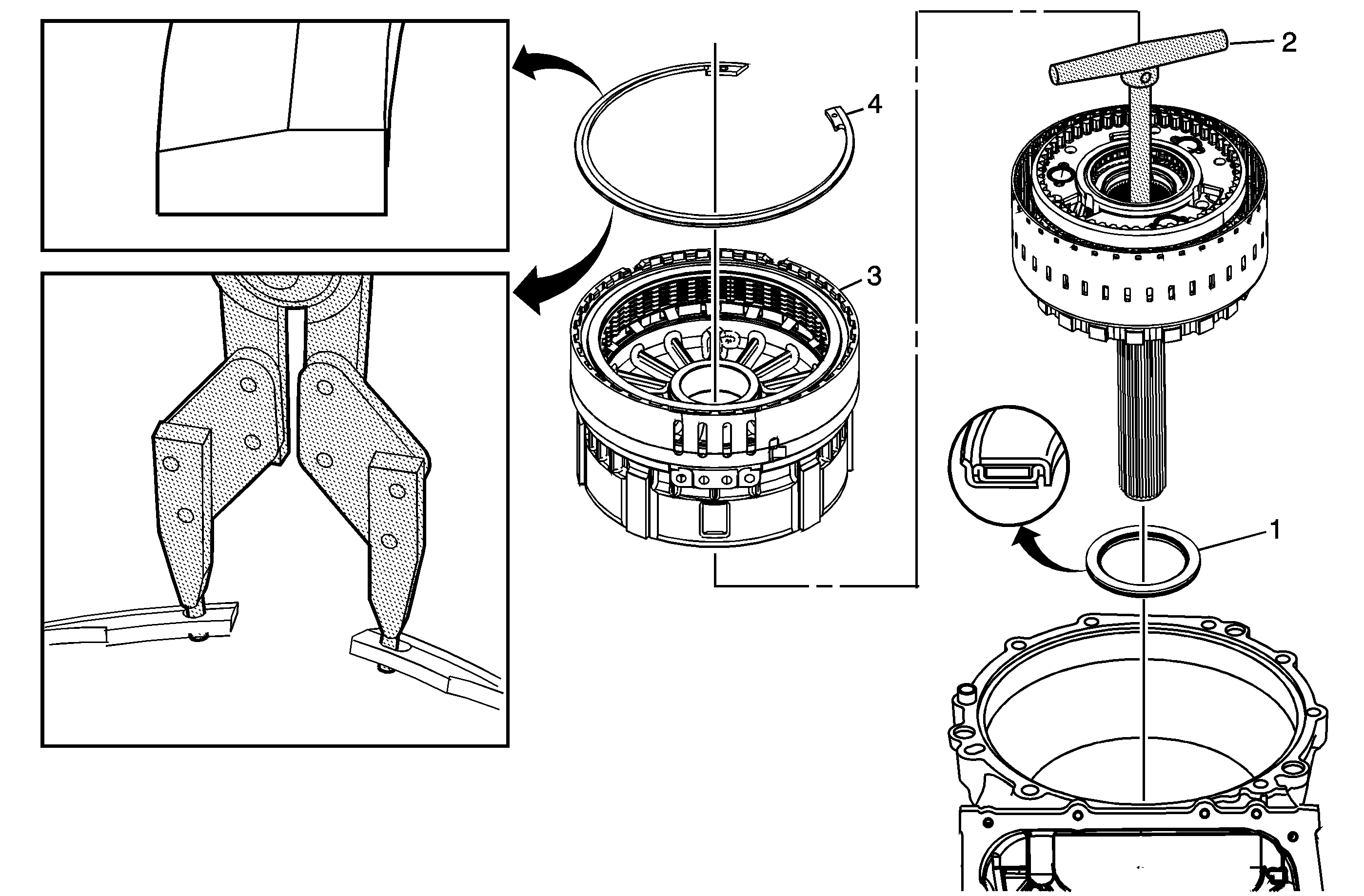
Center Support, Output Carrier and Output Shaft Installation 6L80/6L90

Callout | Component Name | ||||
|---|---|---|---|---|---|
1 | Output Shaft Thrust Bearing Assembly | ||||
2 | Output Carrier Assembly and Output Shaft Assembly Caution: Apply automatic transmission fluid (ATF) to the inside diameter of the output shaft seal before installing the output shaft assembly into the case. Failure to lube the seal may cause the seal to roll during output shaft installation, which will result in transmission damage. Caution: Ensure the DT 47786 is completely threaded into the output shaft assembly. Due to the weight of the assembly, incomplete threading may cause the assembly to break free from the DT 47786, causing component damage. Special ToolDT 47786 Output Carrier/Shaft Lifting Tool | ||||
3 | Center Support Assembly Tip
| ||||
4 | Center Support Retaining Ring Warning: Use care when removing or installing the retaining ring. Ensure the J 45126 and DT 47773 are installed properly onto the retaining ring or bodily injury may occur. Caution: Ensure the retaining ring is installed with the tapered side up, and in the 9 o'clock position from the pan side of the case. Failure to properly install the retaining ring will cause transmission damage. Special Tools
|
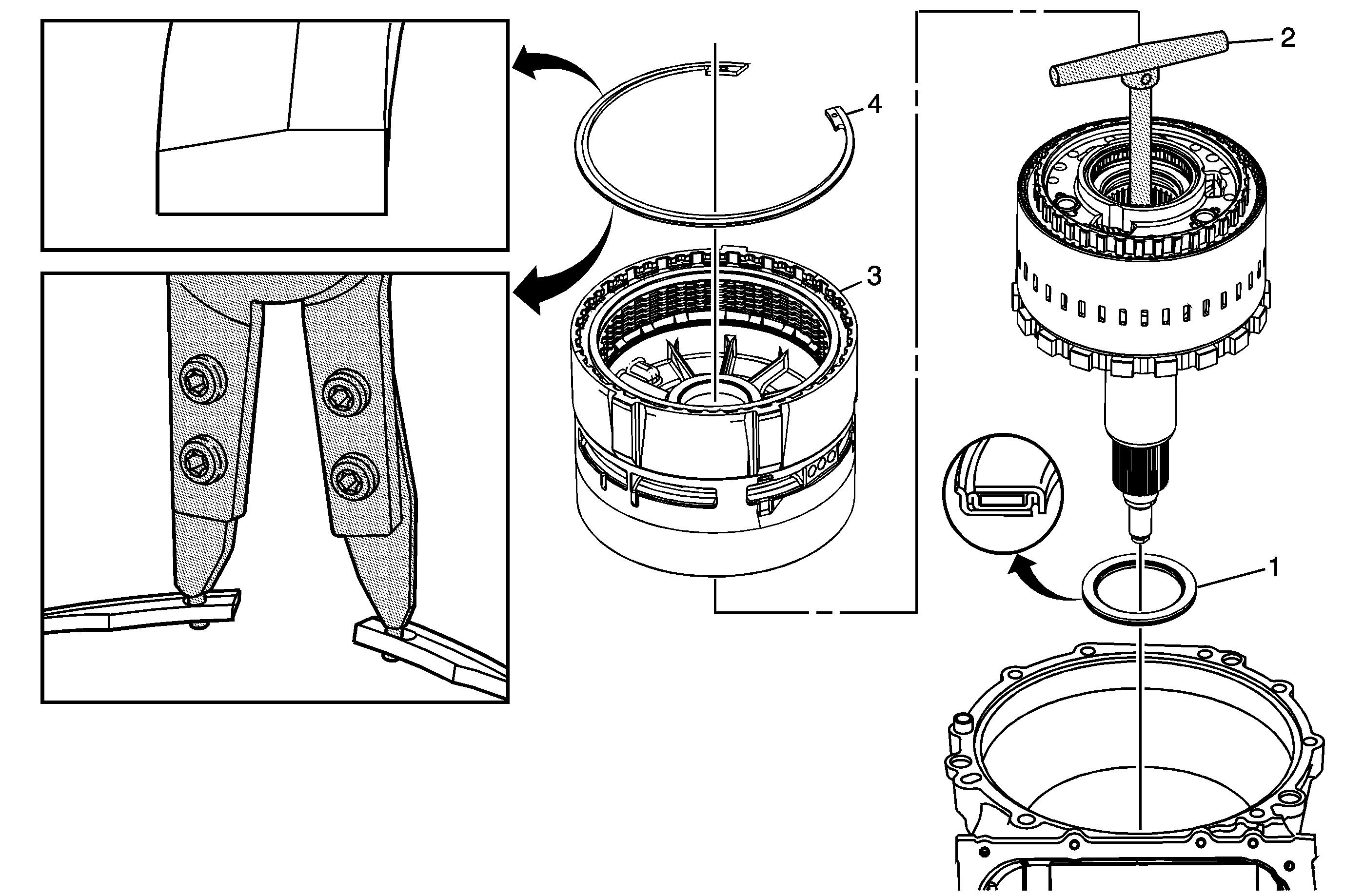
Center Support, Output Carrier and Output Shaft Installation 6L50

Callout | Component Name | ||||
|---|---|---|---|---|---|
1 | Output Shaft Thrust Bearing Assembly | ||||
2 | Output Carrier Assembly and Output Shaft Assembly Caution: Apply automatic transmission fluid (ATF) to the inside diameter of the output shaft seal before installing the output shaft assembly into the case. Failure to lube the seal may cause the seal to roll during output shaft installation, which will result in transmission damage. Caution: Ensure the DT 47786 is completely threaded into the output shaft assembly. Due to the weight of the assembly, incomplete threading may cause the assembly to break free from the DT 47786, causing component damage. Special ToolDT 47786 Output Carrier/Shaft Lifting Tool For equivalent regional tools, refer to Special Tools. | ||||
3 | Center Support Assembly Tip
| ||||
4 | Center Support Retaining Ring Warning: Use care when removing or installing the retaining ring. Ensure the J 45126 is installed properly onto the retaining ring or bodily injury may occur. Caution: Ensure the retaining ring is installed with the tapered side up, and in the 9 o'clock position from the pan side of the case. Failure to properly install the retaining ring will cause transmission damage. Special ToolJ 45126 Snap Ring Pliers For equivalent regional tools, refer to Special Tools. |
