Special Tools
| • | DT-47678 Transmission Holding Fixture
|
| • | DT-49027 Coil Pin Remover and Installer
|
| • | J 3289-20 Holding Fixture
|
| • | J 6125-1B Slide Hammer with Adapter
|
| • | J 35467 One-Way Clutch Tester
|
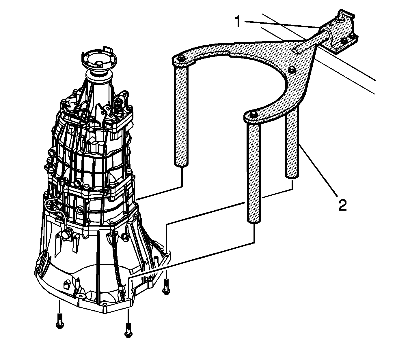
- Install
DT-47678 fixture
(2) to the transmission clutch housing.
- Mount the transmission to a workbench using
J 3289-20 fixture
(1).
- Remove the clutch release cylinder bolts and the clutch release cylinder. Refer to
Clutch Concentric Actuator Cylinder Replacement.
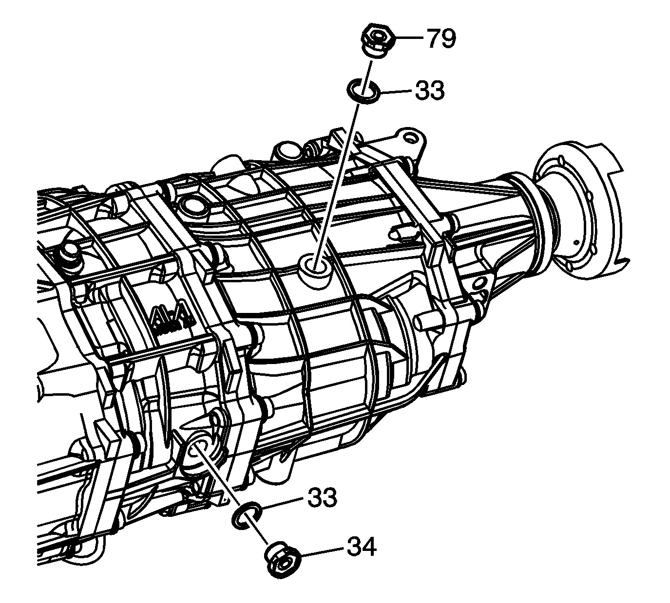
- Remove the fill plug (79) and the washer (33).
- Remove the drain plug (34) and the washer (33) then drain the transmission fluid.
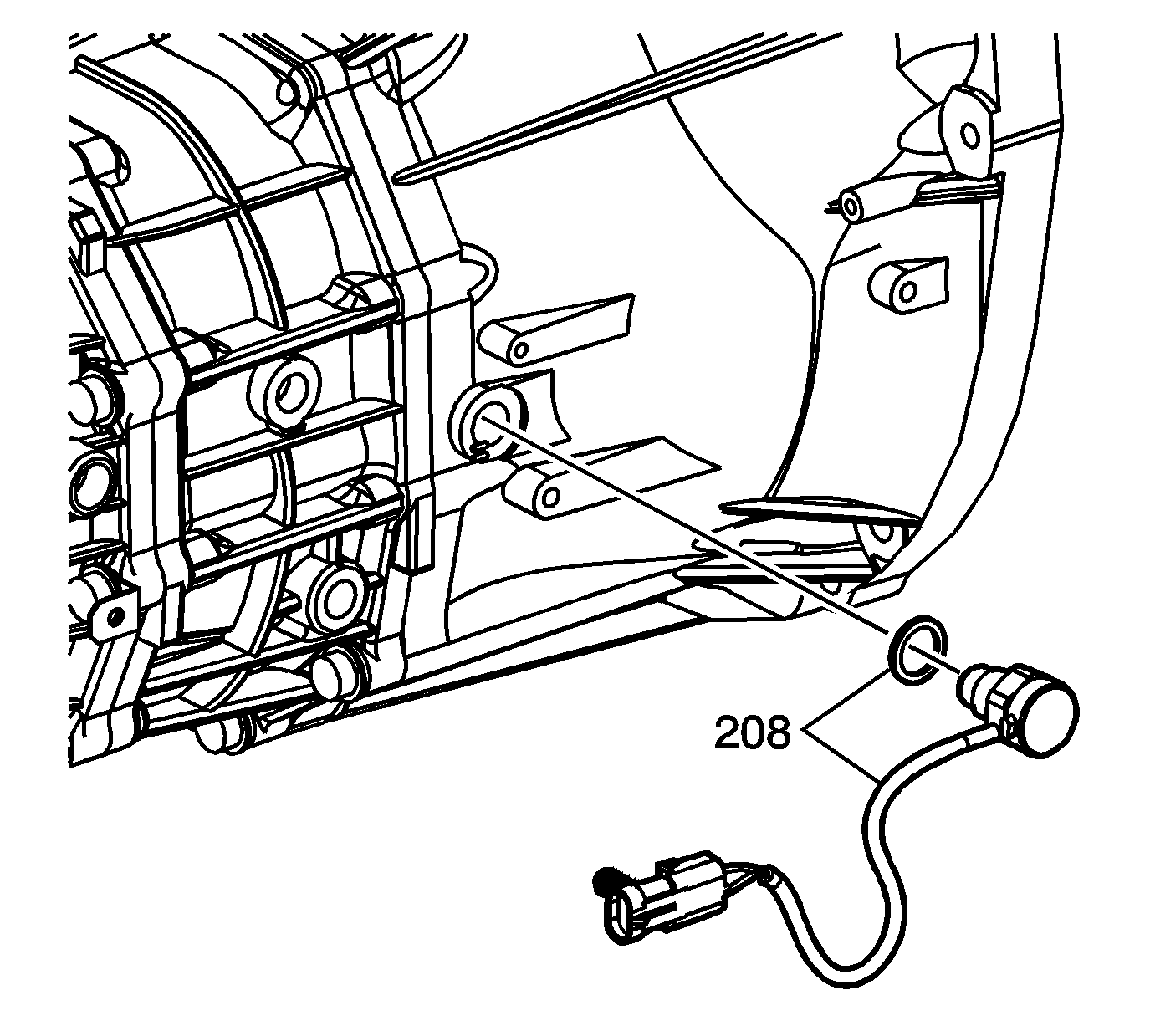
- Remove the backup lamp switch and washer (208) from the case.
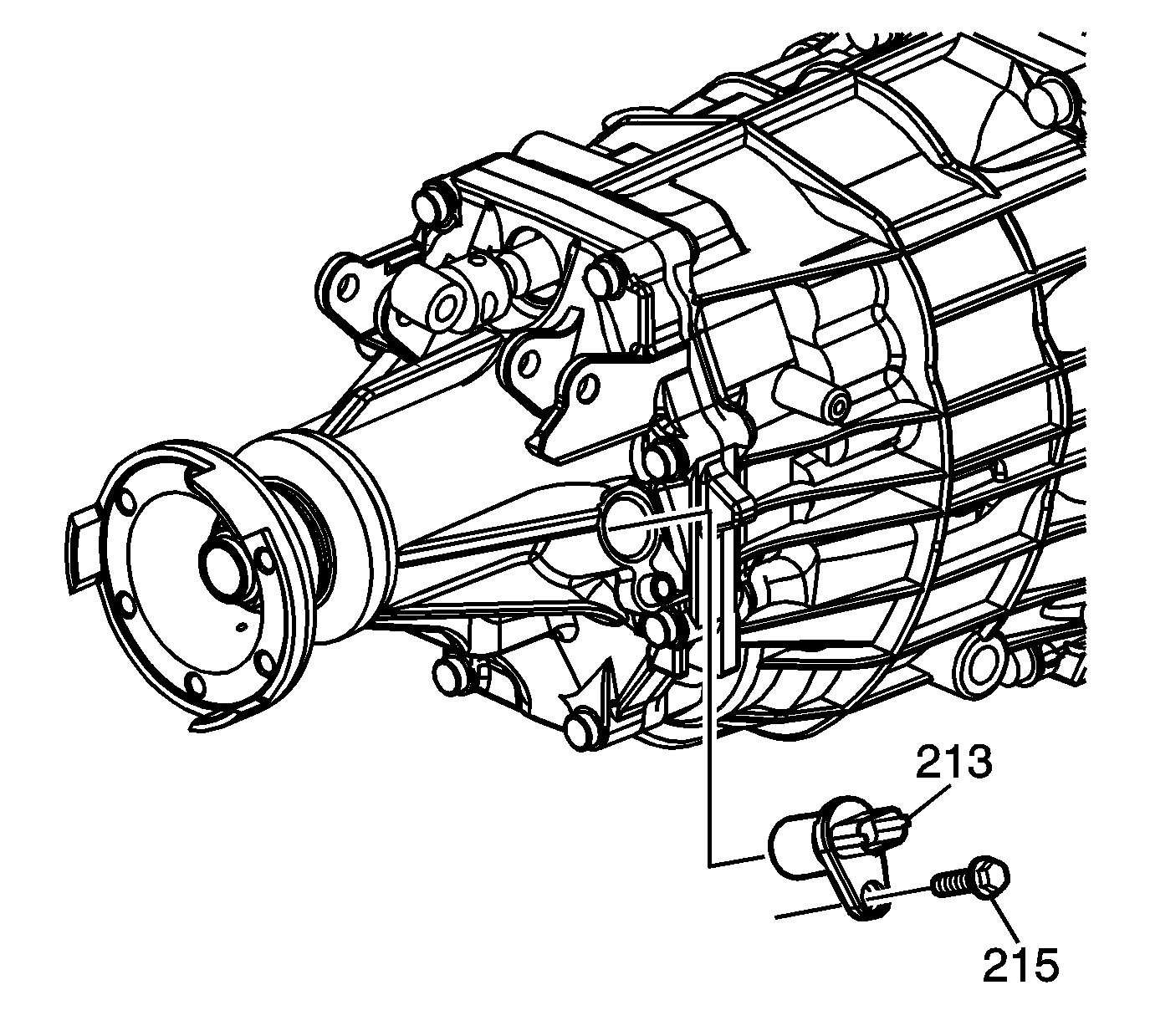
- Remove the output sensor (213) and bolt (215) from the rear extension housing.
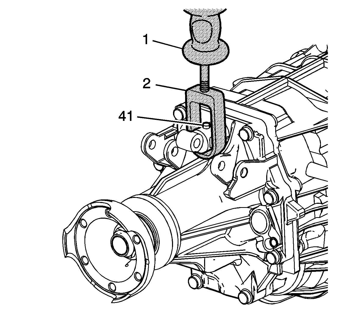
Note: Prior to the shift lever pin removal, the shift control shaft must be shifted forward into the transmission.
- Install
DT-49027-1 coil pin puller
(2) onto
J 6125-1B slide hammer
(1).
- Position
DT-49027-1 puller
(2) directly beneath the shift lever pin (41), then repeatedly pull up on the slide hammer handle until the bottom of the shift lever pin is
flush with the machined O.D. of the shift lever rod universal joint.
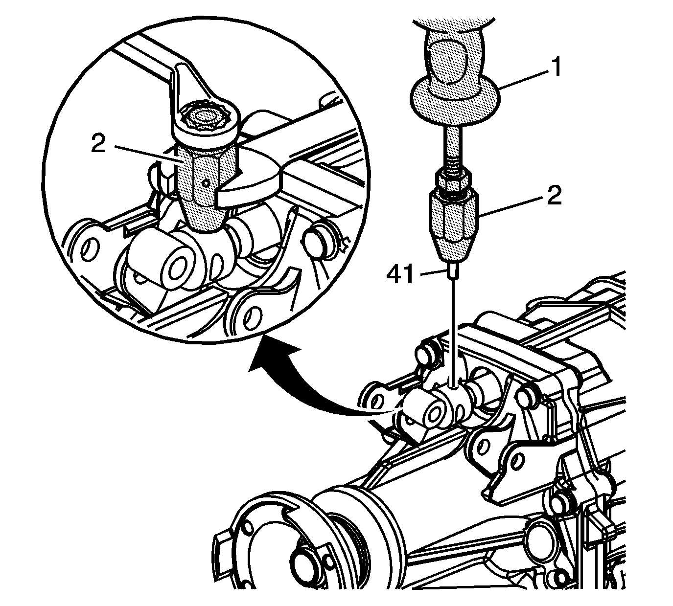
Note: Only rotate the wrench attached to the outer body of
DT-49027-2 coil pin remover
. The wrench attached to the inner body must remain stationary.
- Install
DT-49027-2 coil pin remover
(2) onto the top of the shift lever pin (41) and tighten.
- Install
J 6125-1B slide hammer
(1) onto
DT-49027-2 coil pin remover
(2). Repeatedly, pull
up on the slide hammer handle until the shift lever pin (41) is removed from the shift lever rod universal joint.
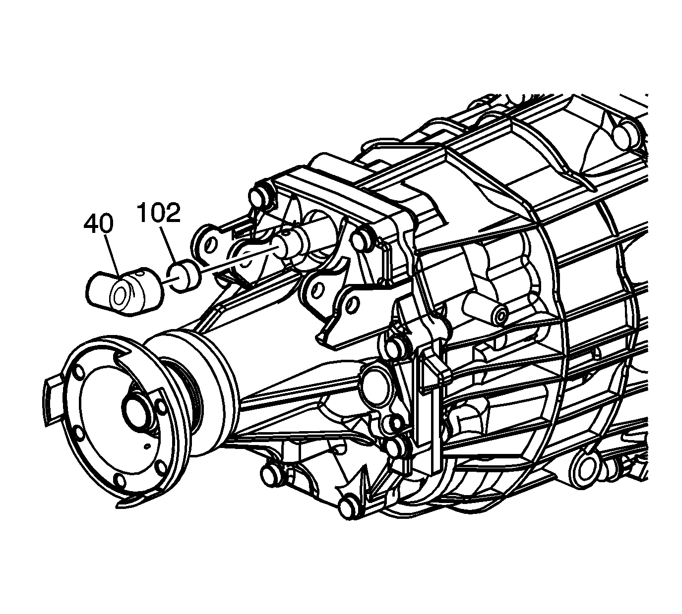
- Remove the shift lever rod universal joint (40) and dampener (102) from the end of the shift control shaft.
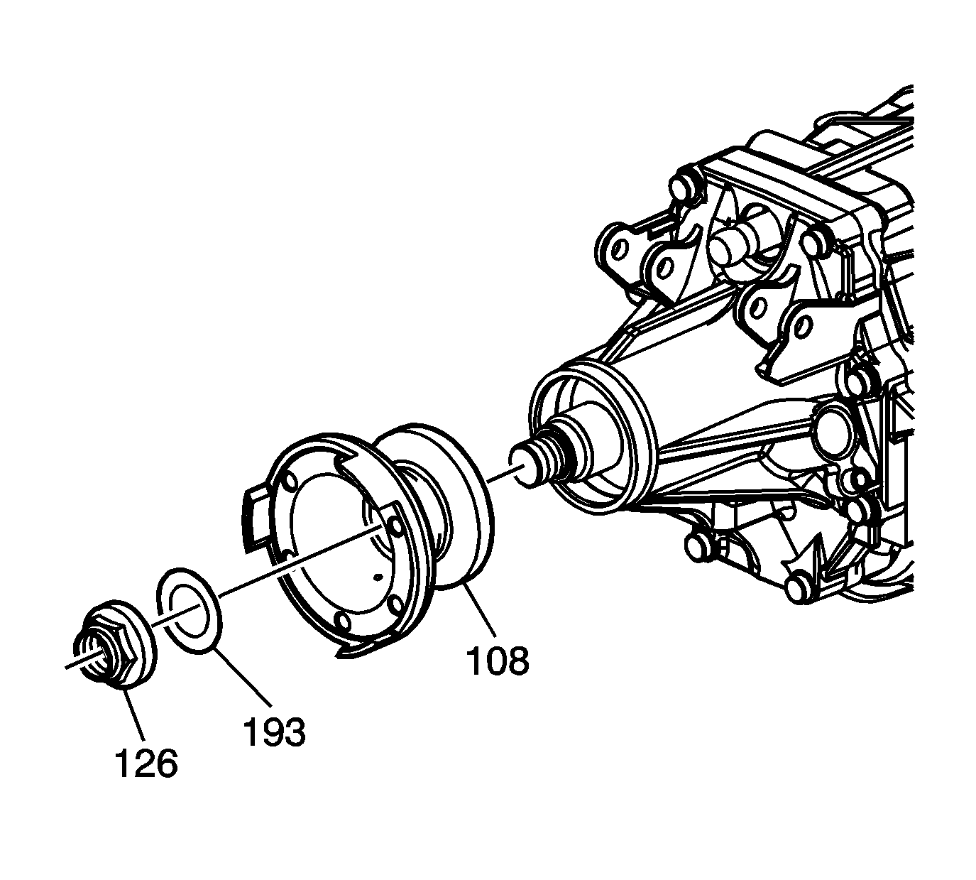
- Using a screwdriver, release the staking of the propshaft flange nut (126).
- Remove the propshaft flange nut (126) and propshaft flange fluid seal (193).
- Remove the propshaft flange (108).
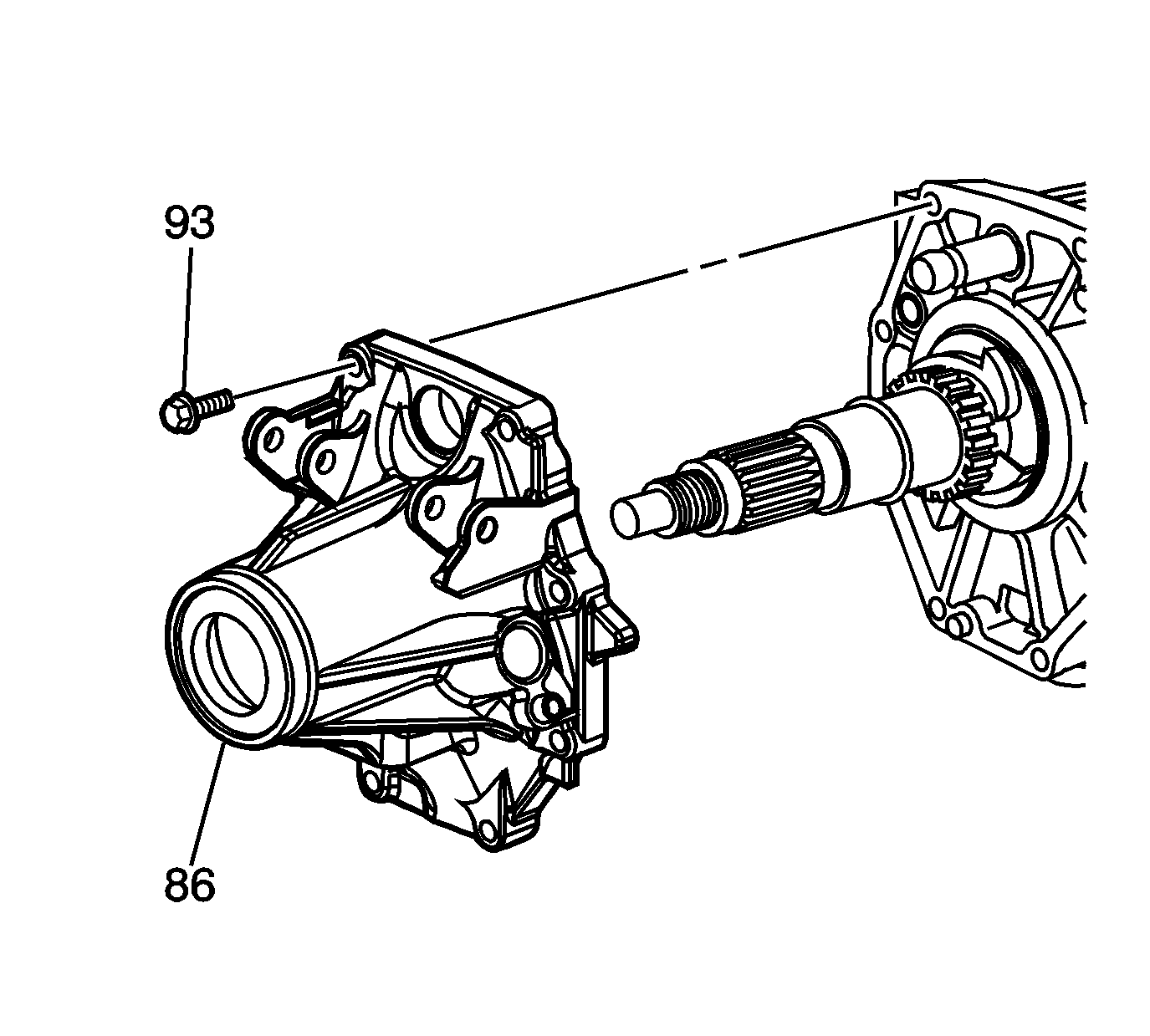
- Remove the 8 bolts (93) from the extension housing (86).
- Remove the extension housing.
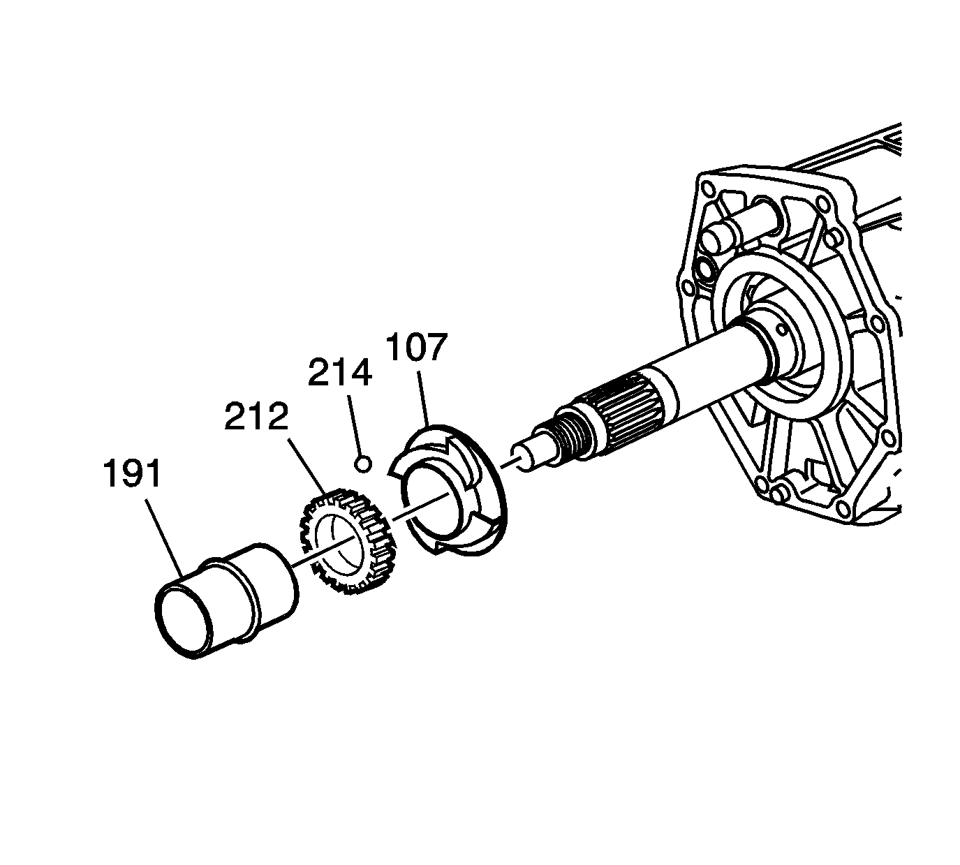
- Remove the rear output shaft rear bearing spacer (191).
- Remove the vehicle speed sensor drive gear (212).
- Remove the locking ball (214).
- Remove the main shaft bearing oil slinger (107).
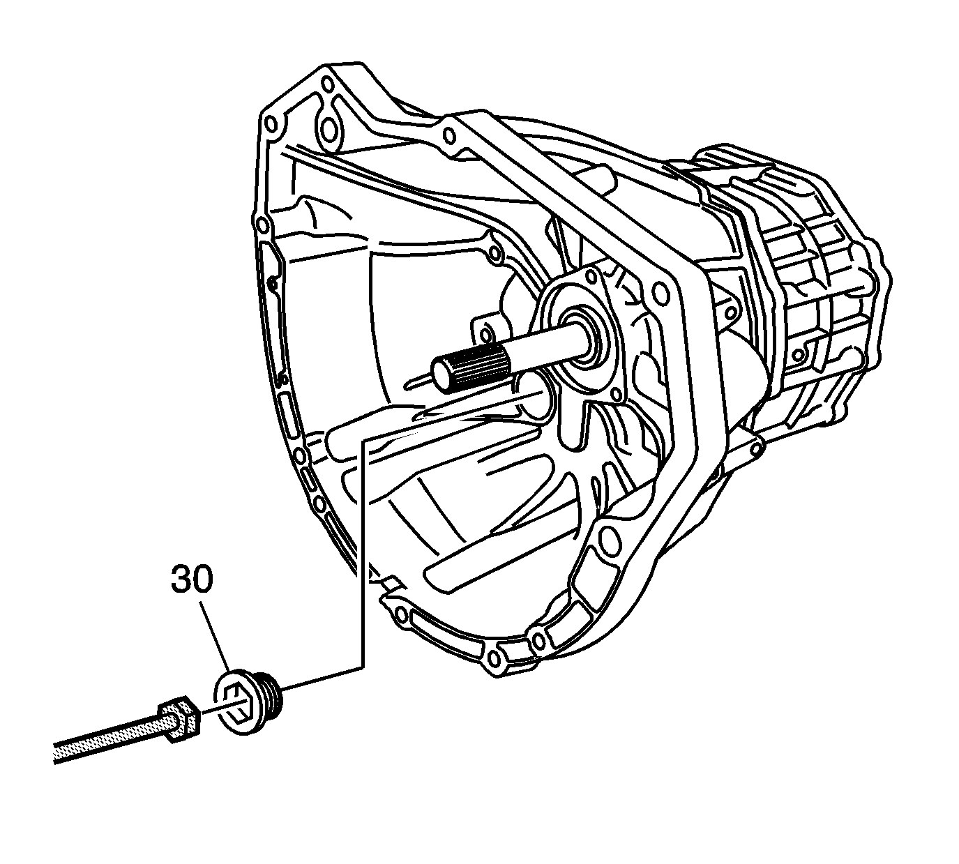
- Using
J 35467 clutch tester
, remove the clutch housing hole plug (30) from the clutch housing.
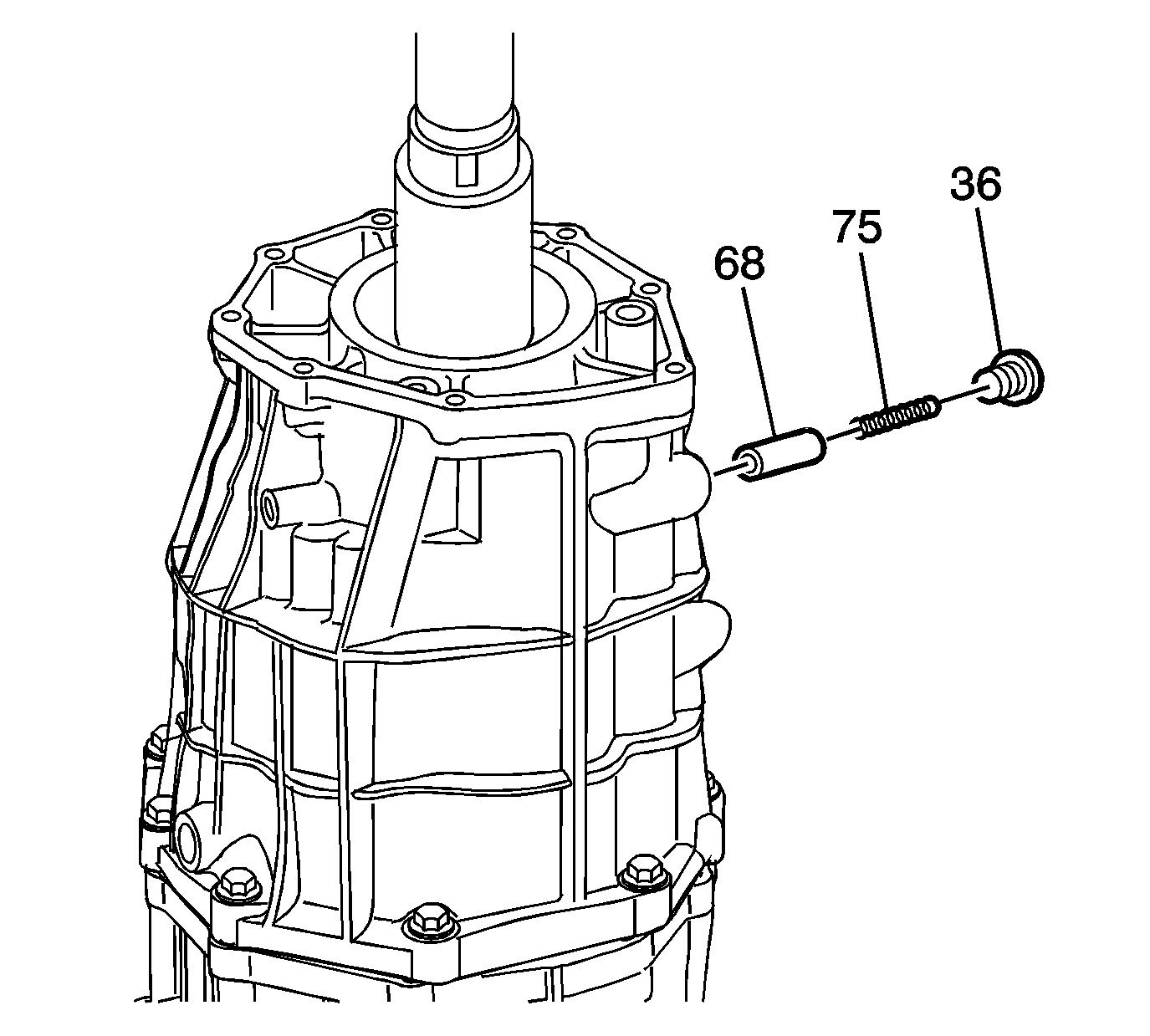
- Remove the following components:
| • | The shift shaft detent plug (36) |
| • | The shift shaft detent spring (75) |
| • | The shift shaft detent pin (68) |
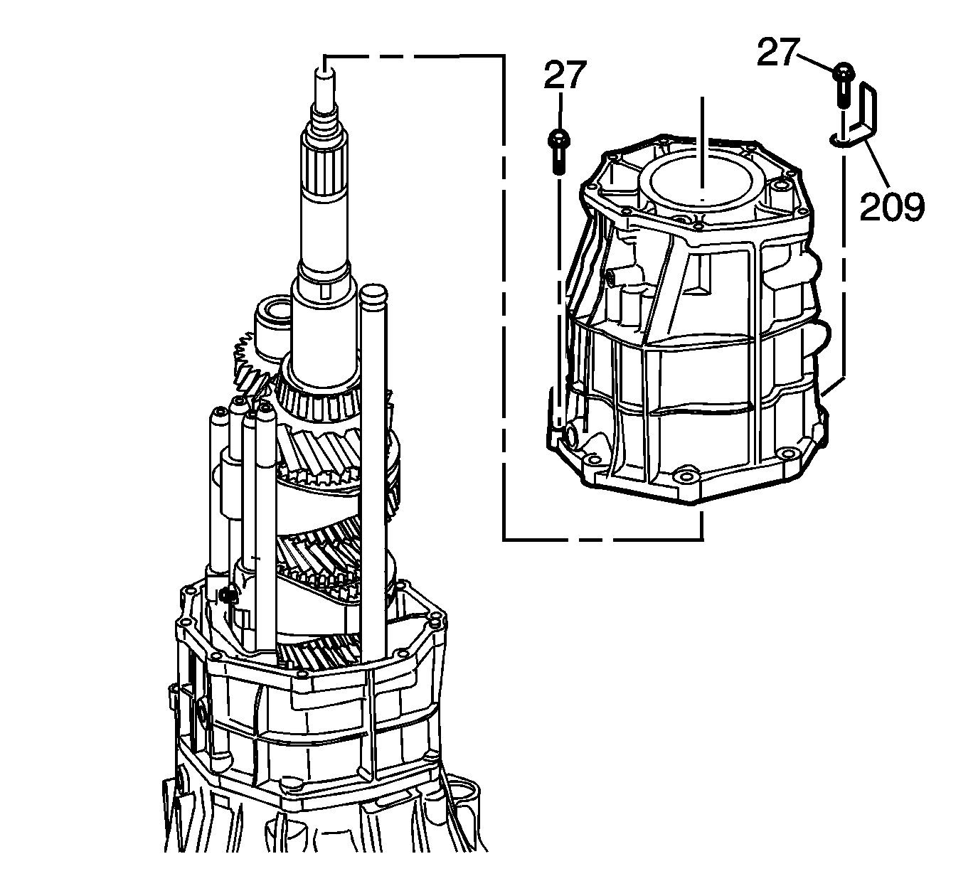
- Remove the 10 bolts (27) and retainer (209) from the rear case housing.
Caution: Refer to Machined Surface Damage Caution in the Preface section.
- Using a soft-face hammer, separate the rear case housing from the intermediate case housing.
- Remove the rear case housing.
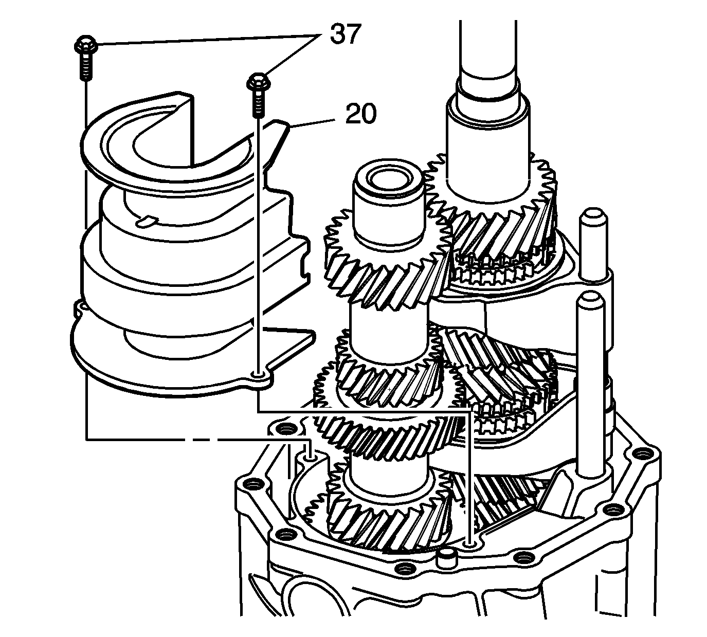
- Remove the 2 oil trough bolts (37) and oil trough (20).
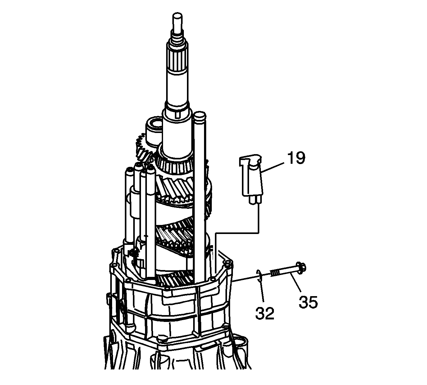
- Remove the oil trough pipe (19).
- Remove the reverse idler gear shaft bolt (35) and gasket (32).
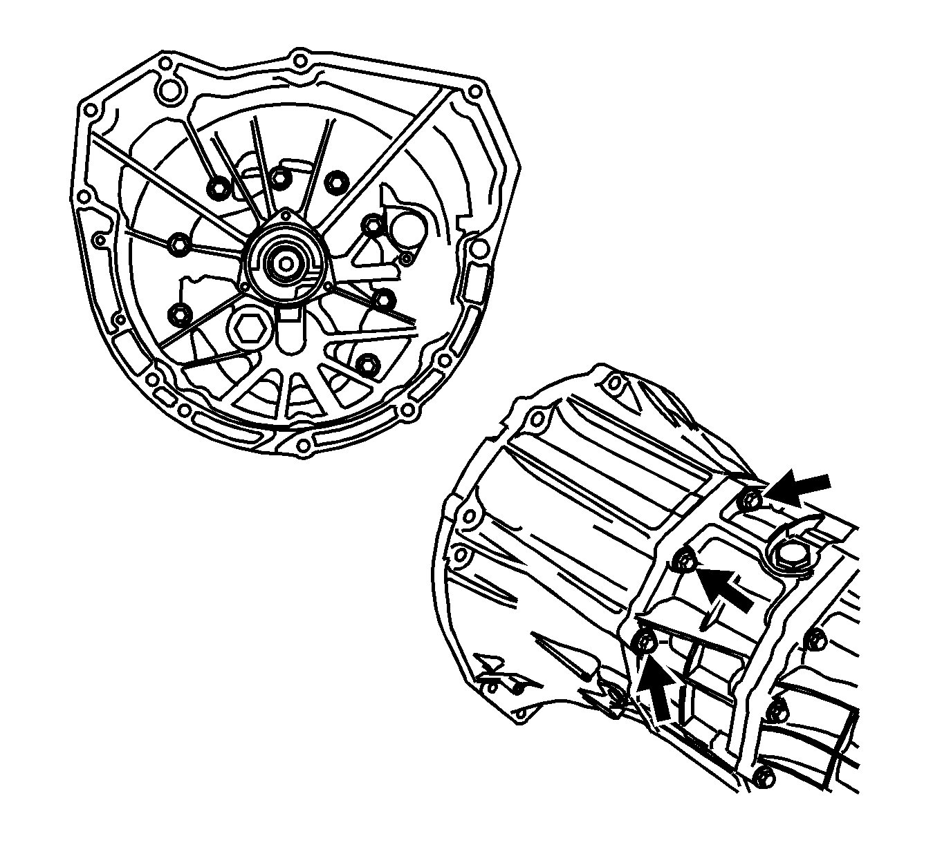
- Remove the 11 flange bolts retaining the clutch housing. This includes 8 bolts from the front and 3 bolts from the rear.
Caution: Refer to Machined Surface Damage Caution in the Preface section.
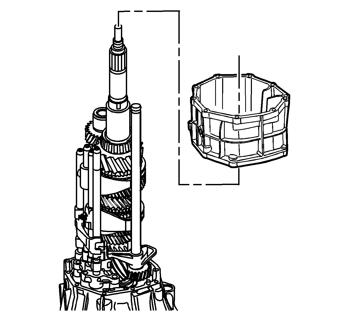
- Using a soft-face hammer, separate the intermediate case from the front clutch housing.
- Remove the intermediate case housing.
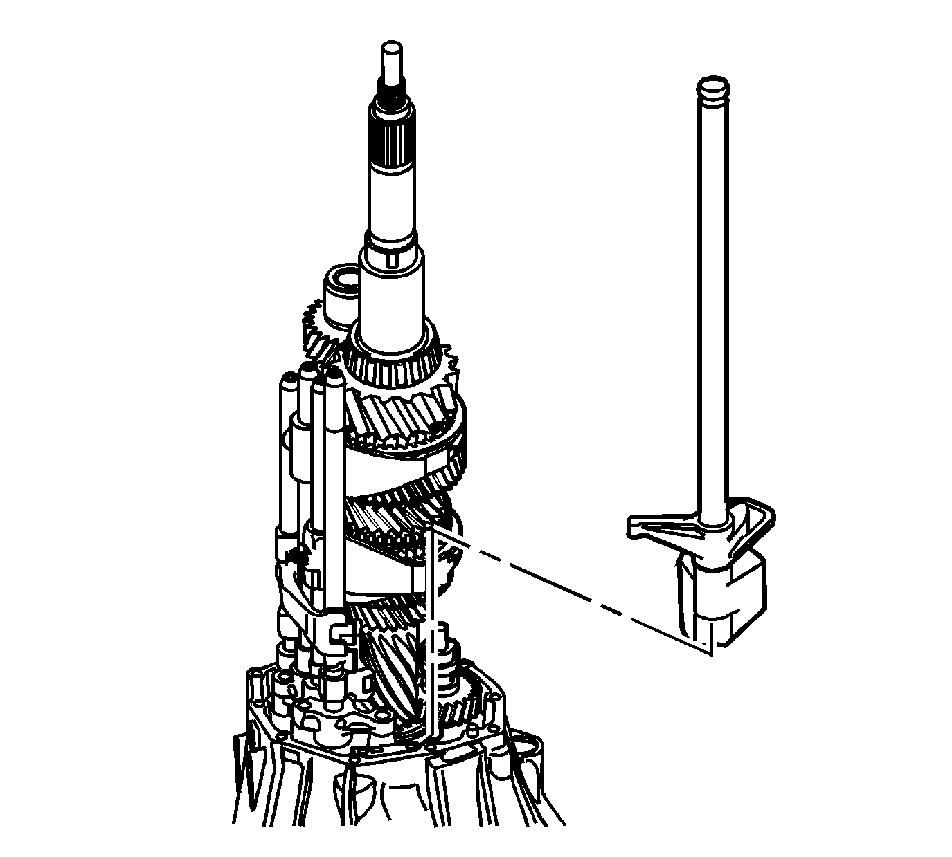
- Remove the shift shaft selector lever.
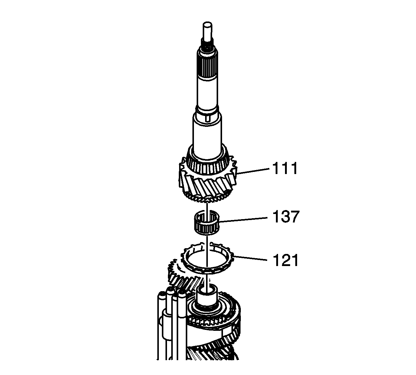
- Remove the rear output shaft (111), input shaft bearing (137) and blocking ring (121) from the 6th gear synchronizer assembly.
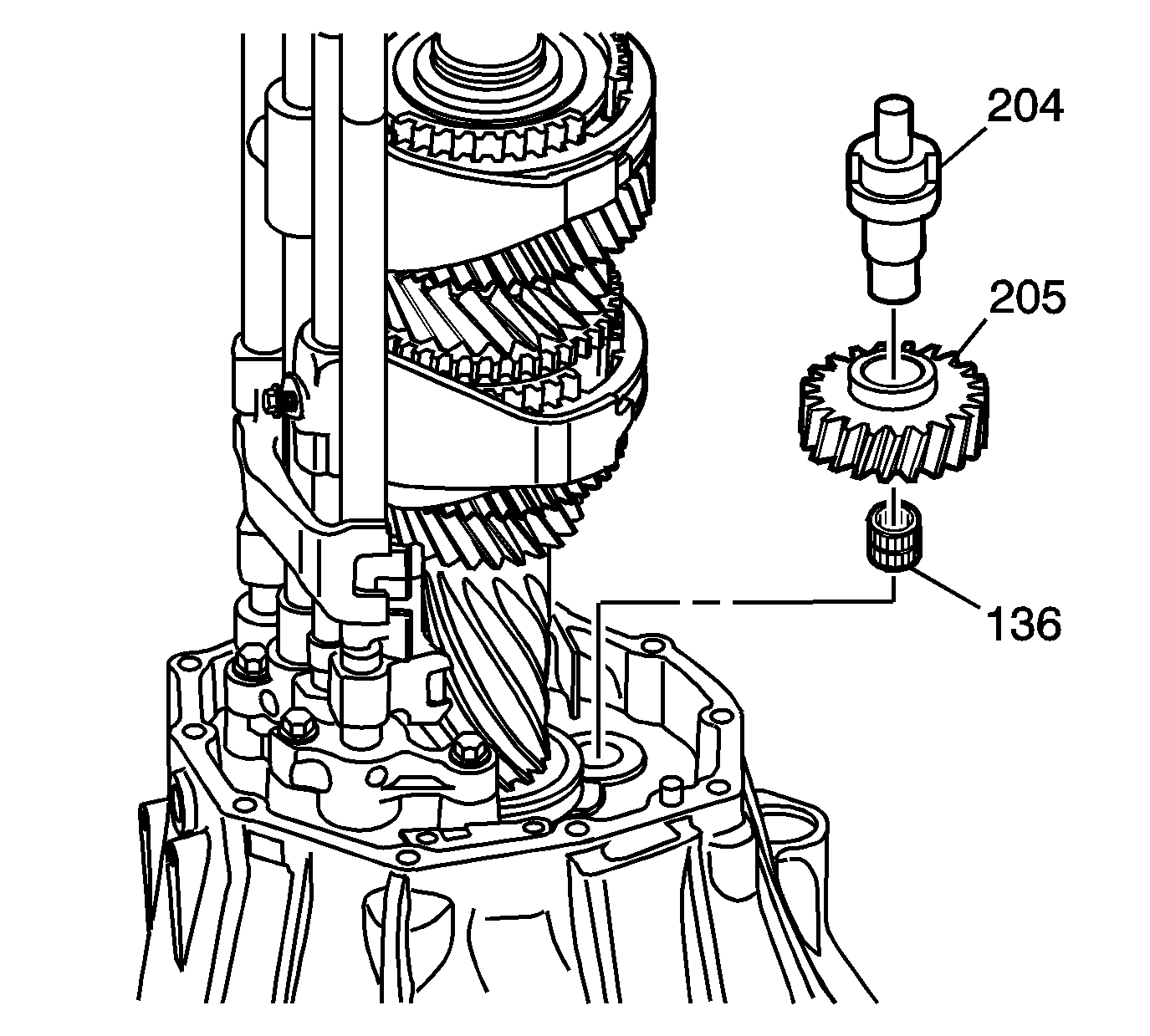
- Remove the reverse idler gear bearing (136), reverse idler gear (205) and the reverse idler gear shaft (204).
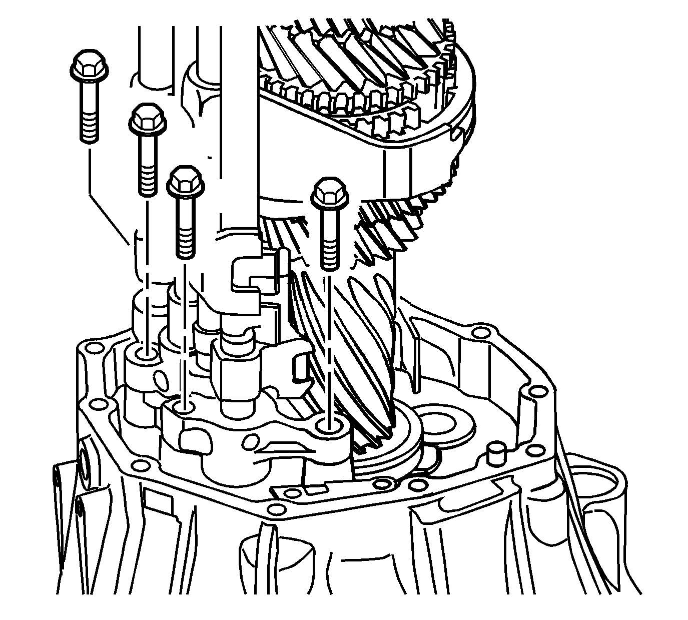
- Remove the 4 bracket bolts from the shift counter lever bracket.
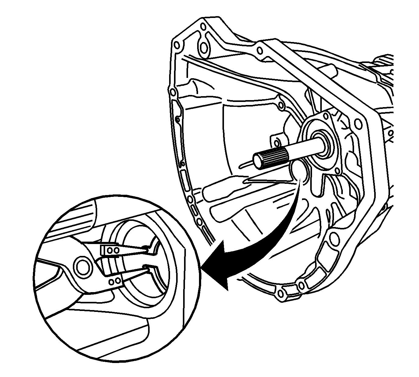
- Stretch snap ring on the front countershaft bearing. Maintain stretch.
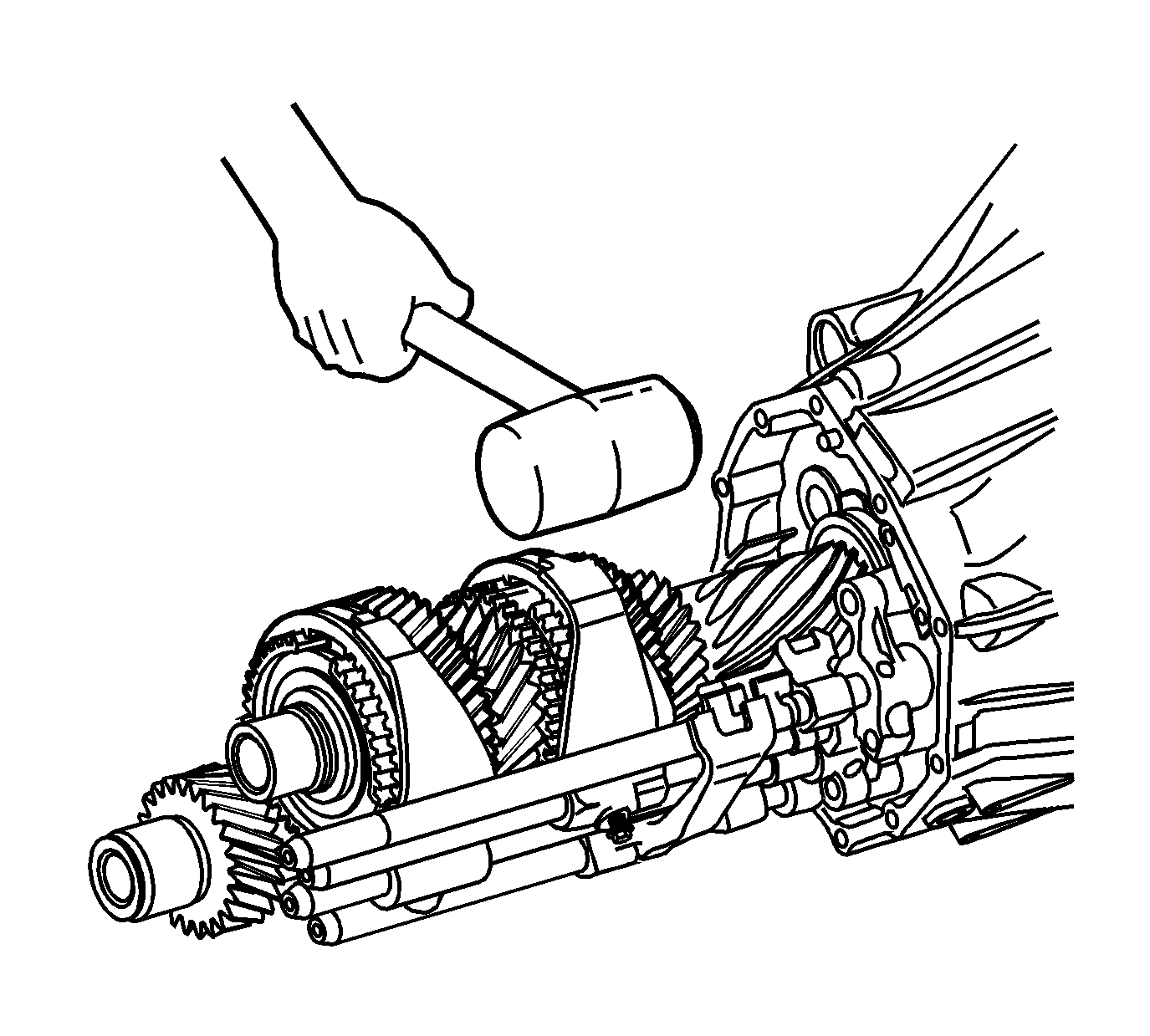
- Using a rubber hammer, tap on transmission front case in order to disengage the countershaft bearing's snap ring.
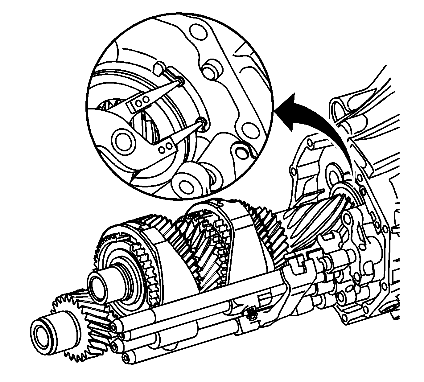
- Stretch the snap ring on the rear input shaft bearing. Maintain stretch.

- Hold the countershaft. Using a soft rubber hammer tap on the transmission front case in order to disengage the snap ring. Separate the input shaft and countershaft from clutch housing.
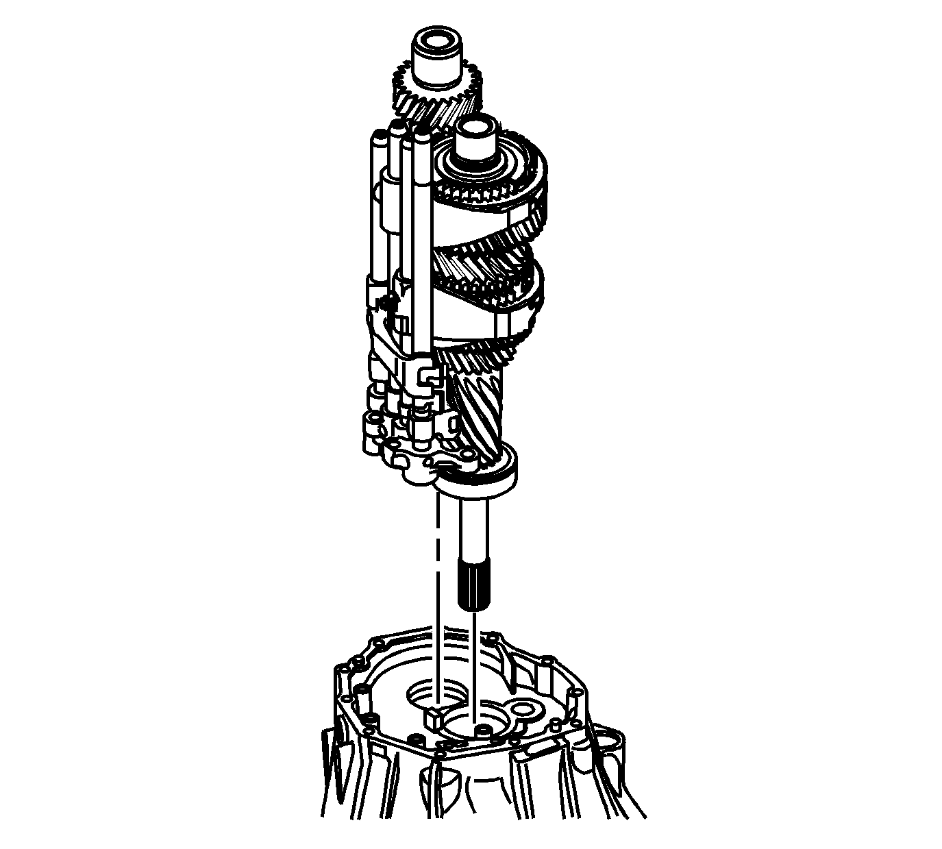
- Remove the input shaft, countershaft and shift rails as an assembly.
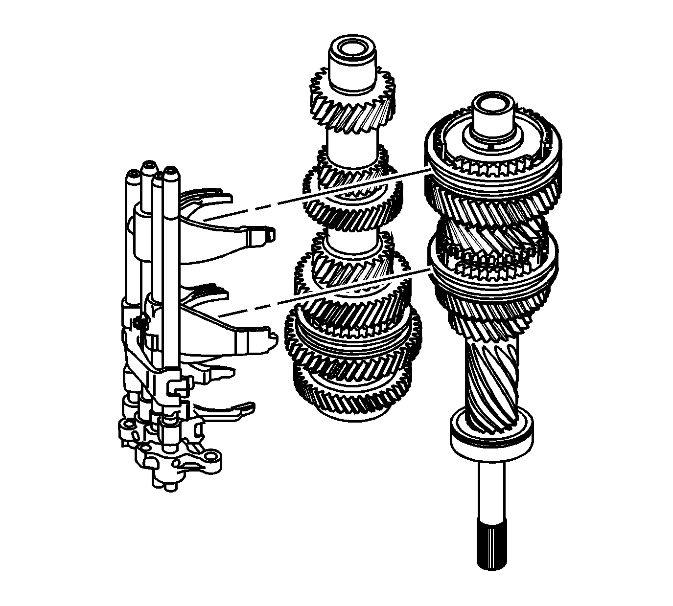
- Separate the shift rails, the input shaft and countershaft.


