For 1990-2009 cars only
Special Tools
| • | DT-48636 Flange Holder |
| • | J 6125-1B Slide Hammer |
| • | J 23129 Universal Seal Remover |
| • | J 29873 Injector Nozzle Socket 30 mm |
| • | J 44765 Seal Installer |
| • | J 45019 Flange and Pinion Cage Remover |
Removal Procedure
- Place the transmission in neutral.
- Raise and support the vehicle. Refer to Lifting and Jacking the Vehicle.
- Remove the propeller shaft. Refer to Rear Propeller Shaft Replacement.
- Using a flat-bladed tool, disengage the staked portion of the drive flange nut.
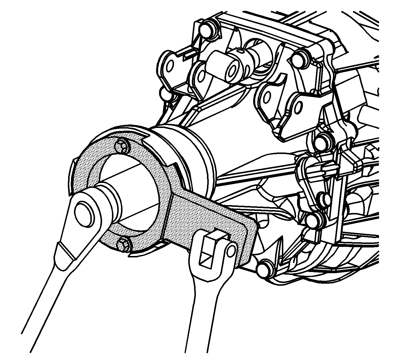
- Install the DT-48636 to the drive flange.
- While holding DT-48636 , loosen the flange nut using J 29873 .
- Remove the DT-48636 .
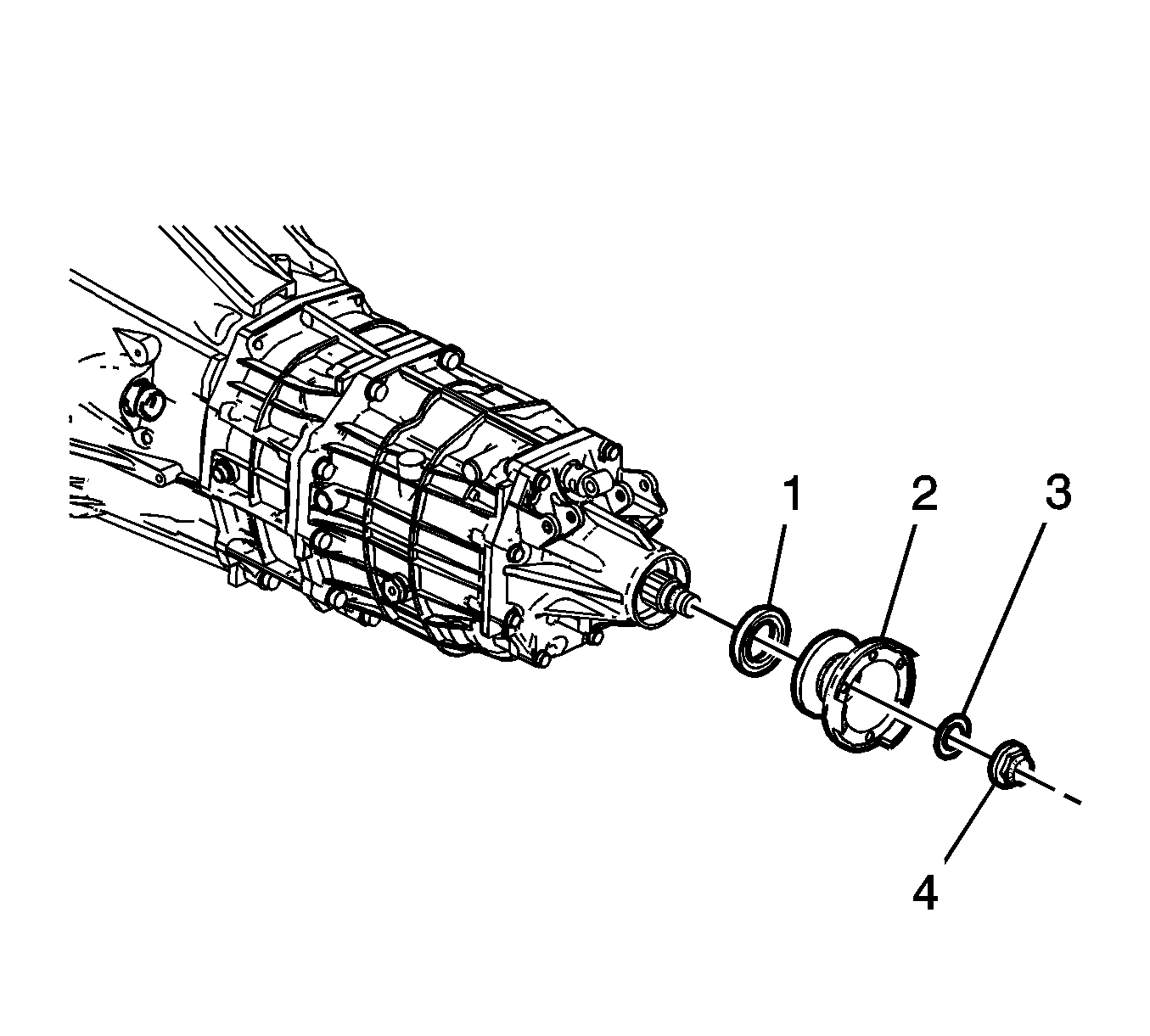
- Remove and discard the drive flange nut (4).
- Remove and discard the drive flange fluid seal (3).
- Using J 45019 , remove the drive flange (2).
- Using J 6125-1B and J 23129 remove the transmission case extension seal (1).
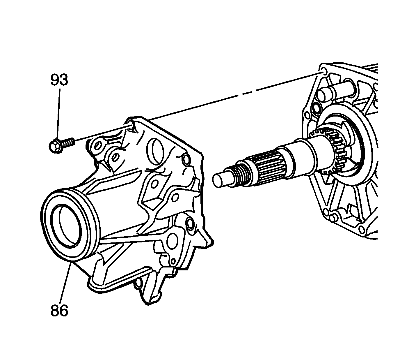
- Remove the rear extension housing (86). Refer to Transmission Disassemble.
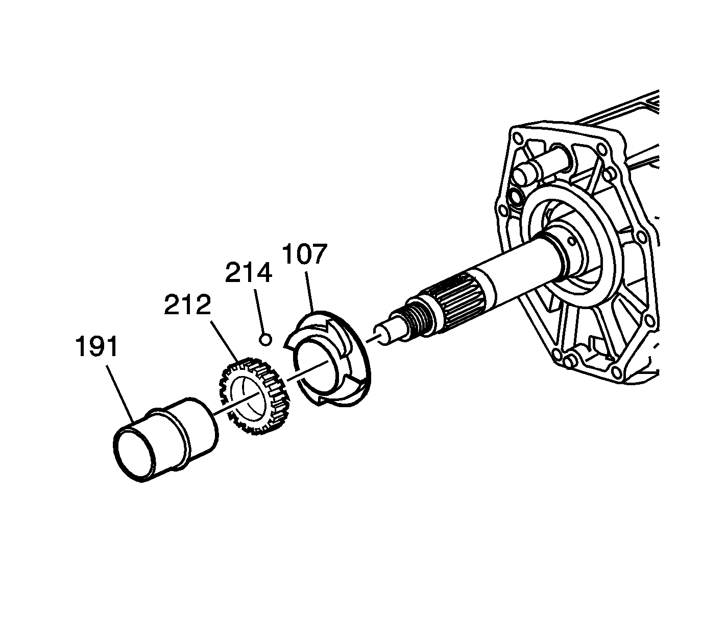
- Remove and discard the rear output shaft rear bearing spacer (191).
Note: The rear output shaft rear bearing spacer must be replaced, and the bearing preload must be adjusted every time the rear drive flange is removed from the transmission.
Installation Procedure
- Install a NEW rear output shaft rear bearing spacer (191).
- Install the rear extension housing (86). Refer to Transmission Assemble.
- Using J 44765 install the new transmission case extension seal (1).
- Install the drive flange (2) to the transmission output shaft.
- Install a NEW drive flange fluid seal (3).
- Install a NEW drive flange nut (4) until finger tight.


Note: Install the seal onto the tool before installing into the case to prevent damage to the seal.
Preload Adjustment Procedure
- Shift the transmission into any gear.
- Attach DT-48636 to the output flange.
- Hold DT-48636 in order to prevent the output flange from rotating. Using J 29873 tighten the output flange nut. Tighten until the looseness is minimal.
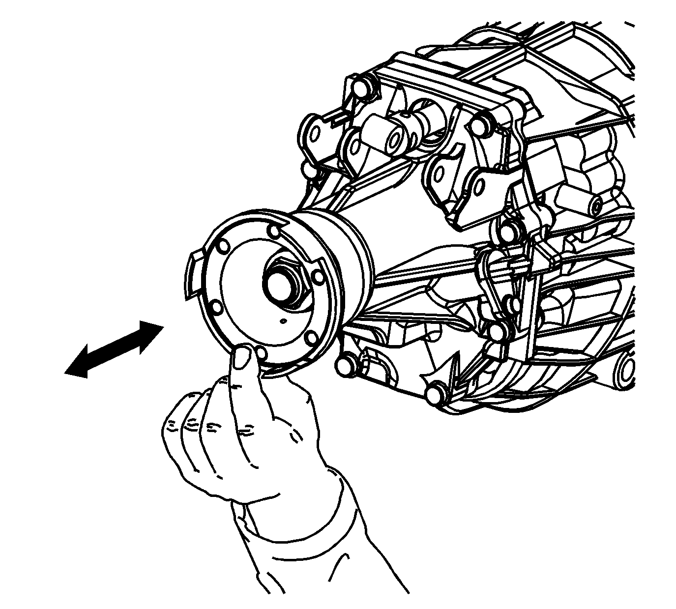
- Verify looseness by shaking the output shaft longitudinally.
- Remove DT-48636 from the output flange.
- Shift the transmission into NEUTRAL.
- Rotate the output flange several times in order to seat the bearings.
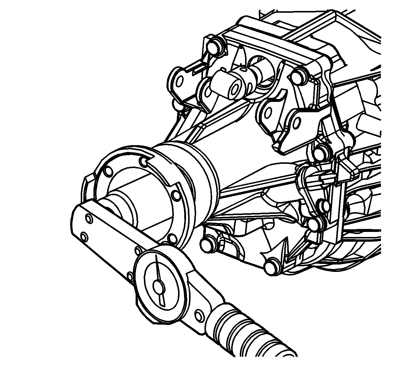
- Measure the rotational torque/drag torque of the output flange by using a suitable tool. Record this initial rotational torque measurement as value A.
- Attach DT-48636 to the output flange.
- Shift the transmission into any gear.
- Tighten the nut to 220-565 N·m (162-417 lb ft).
- Remove the DT-48636 from the output flange.
- Shift the transmission into NEUTRAL.
- Rotate the output flange several times in order to seat the bearings.
- Measure the rotational torque/drag torque of the output flange by using a suitable tool. Record this rotational torque measurement as value B.
- Subtract value A from value B. Verify that the resulting measurement is within the specified range.
- Repeat the previous steps until you have confirmed that the rotational torque specification is reached, then stake the nut in place. If the rotational torque requirement has been exceeded, replace the spacer and repeat the steps above.
- At the correct location, stake the drive flange nut.
- Install the propeller shaft. Refer to Rear Propeller Shaft Replacement.
- Lower the vehicle.


Caution: Refer to Fastener Caution in the Preface section.
Specification
The rotational torque specification is 0.45-1.35 N·m (4-12 lb in).
