Special Tools
| • | DT 47678 Transmission Holding Flange
|
| • | DT 47678-10 Transmission Holding Flange Adapter
|
| • | DT 49293 Gear Select/Skip Shift Solenoid Socket
|
| • | J 08614A Pinion Flange Holder and Remover
|
| • | J 3289-20 Holding Fixture
|
| • | J 36017 Valve Seal Remover
|
| • | J 36850 Transjel® Lubricant Assembly Lube
|
| • | J 39441-20 Fifth Gear Installer Adapter
|
| • | J 39441-30 5th/6th Driven Gear Installer
|
| • | J 39442 Mainshaft and Countershaft Press Adapter
|
| • | J 44395 Transmission Holding Fixture
|
Shift Shaft Assemblies and Gear Clusters Installation
- Lubricate all components as assembly progresses, using
J 36850 transjel® lubricant
.
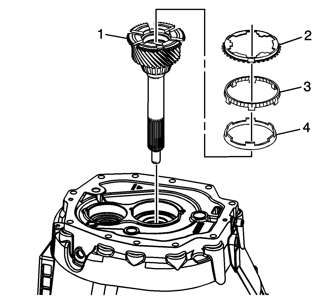
- Install the input shaft (1) in the clutch housing.
- Install the 4th gear blocking assembly:
| 3.1. | Install the 4th speed drive gear inner cone (4). |
| 3.2. | Install the 4th speed drive gear outer cone (3). |
| 3.3. | Install the 4th speed drive gear blocking ring (2). |
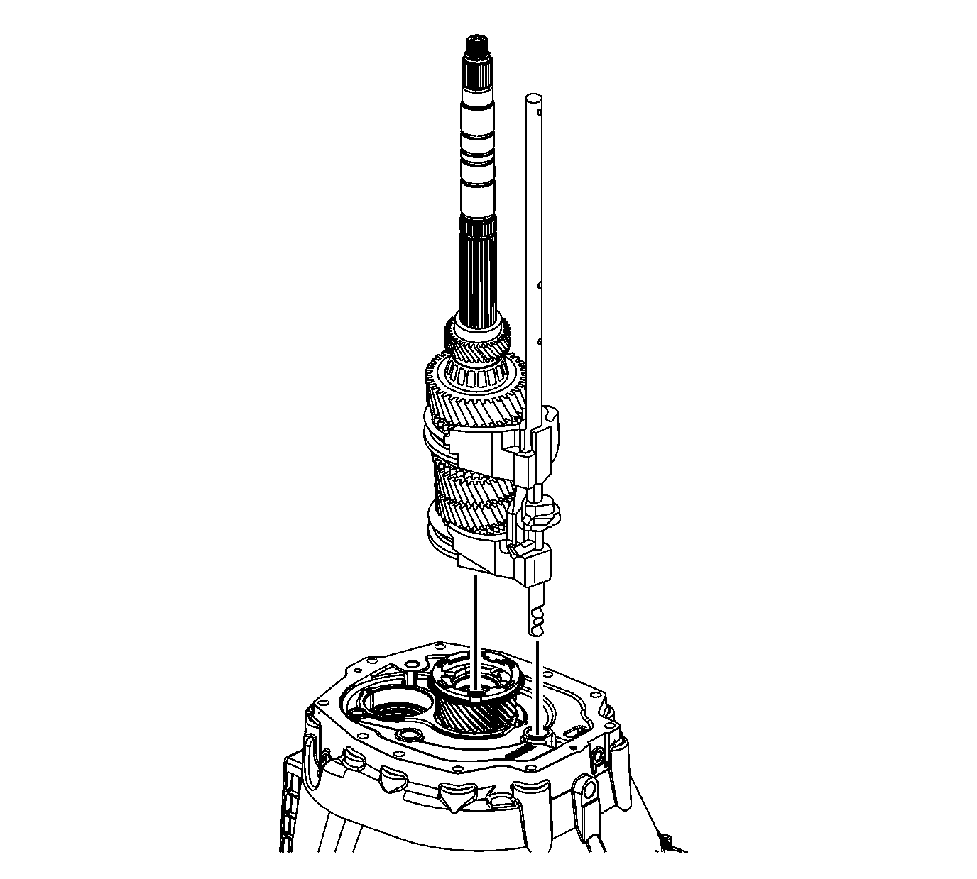
Note: In order for the shift forks to properly line up with the synchronizers, the shift shaft assembly must be assembled correctly. Refer to
Shift Shaft and Fork Assemblies Assemble.
- Assemble the shift shaft to the mainshaft.
- Install the mainshaft and the shift shaft assembly into the clutch housing.
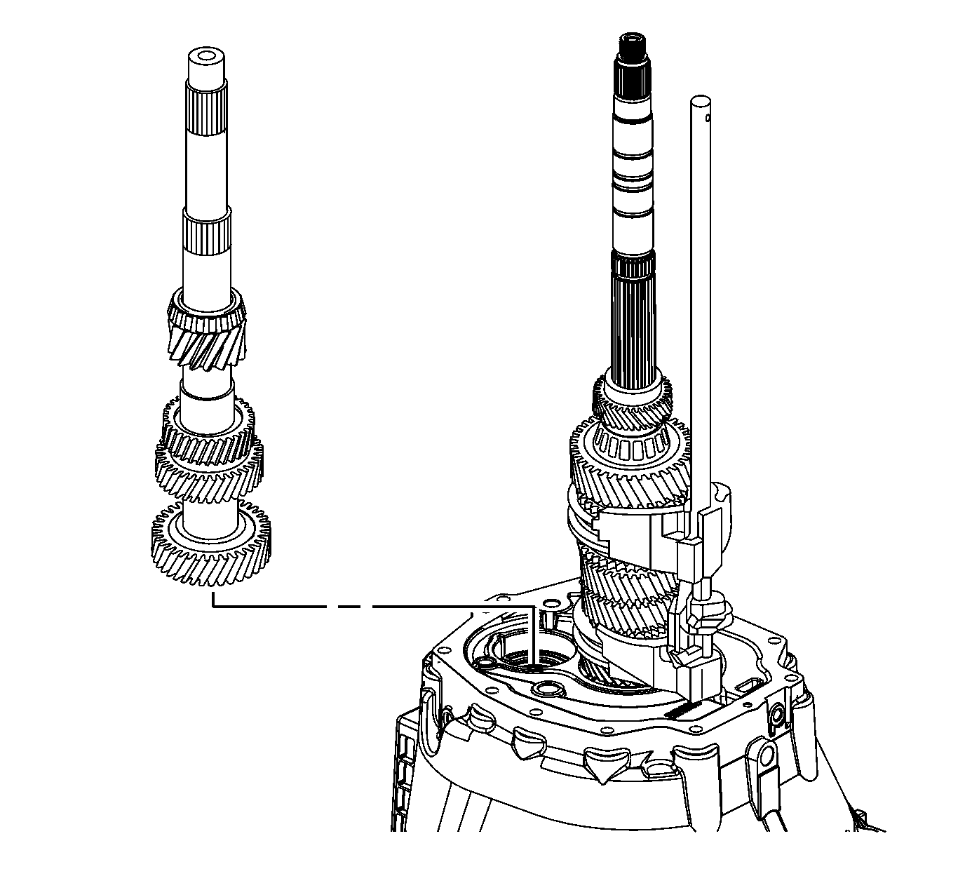
- Install the countershaft assembly using the following sequence:
| 6.1. | Lift up the mainshaft assembly enough in order to install the countershaft assembly. |
| 6.2. | Install the countershaft assembly. |
| 6.3. | Lift the mainshaft assembly enough in order to rotate the input shaft to engage the synchronizer keys with 4th gear blocking ring. |
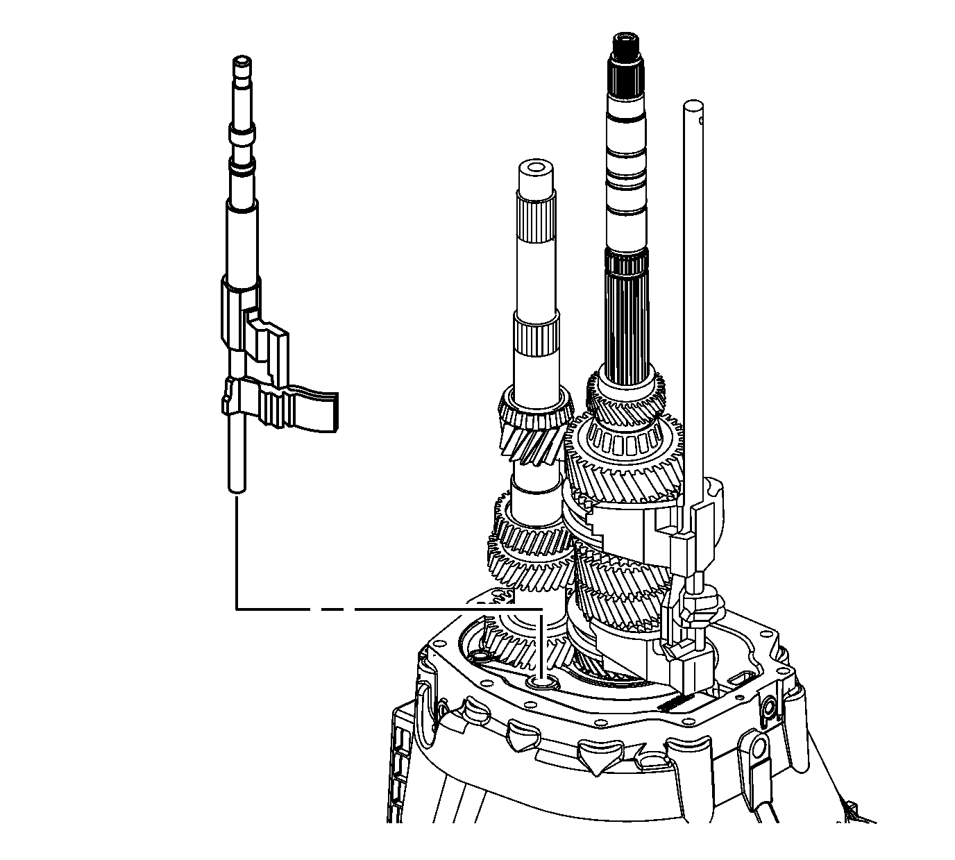
- Install the 5th/6th and the reverse shift shaft.
Align the slots of the shift shaft levers with the interlock plate.
Oil Filter Installation
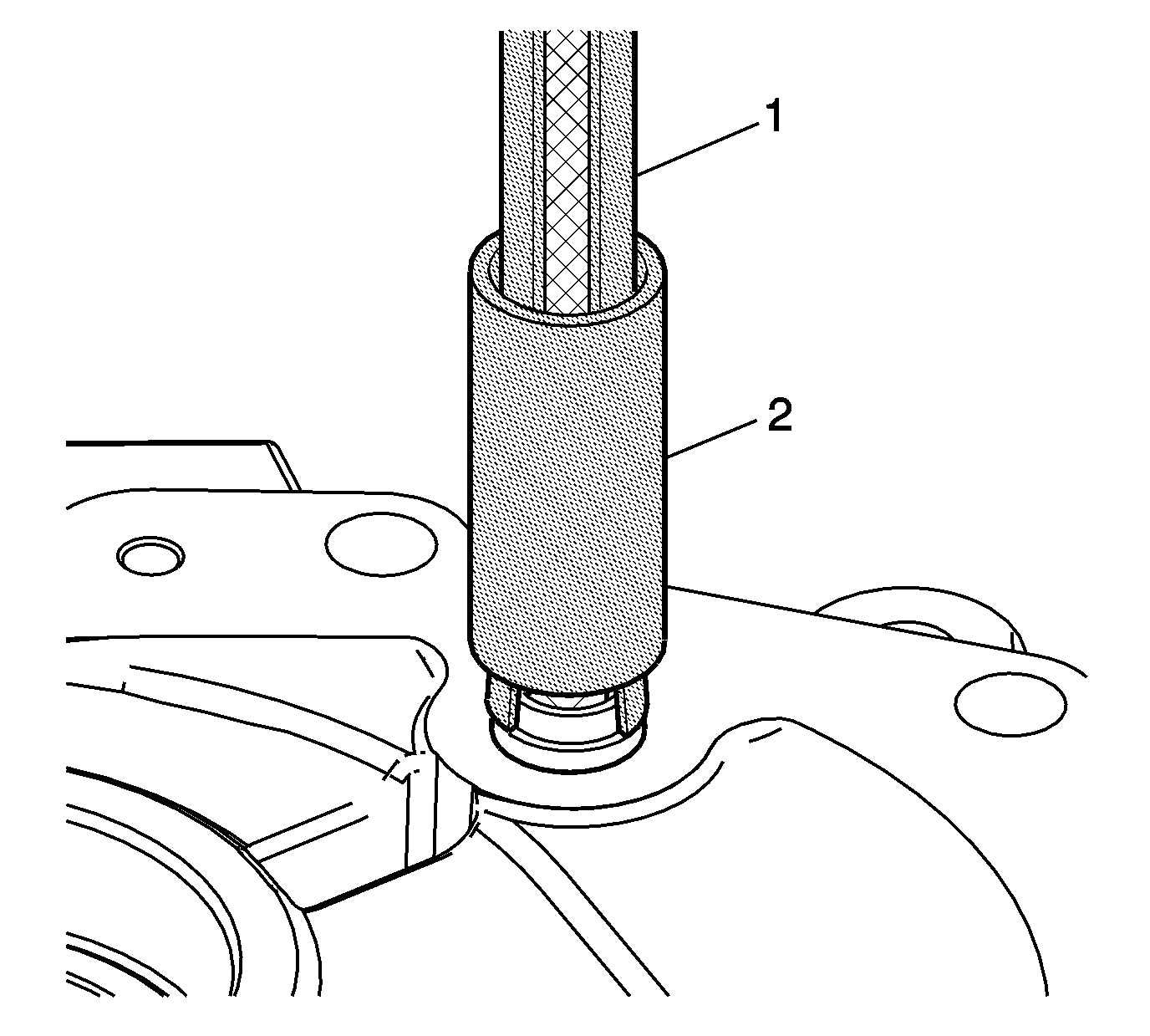
- Attach the
J 36017 remover
(1) within the groove at the base of the oil filter assembly. Slide the collar (2) of the tool down to grasp the oil filter assembly.
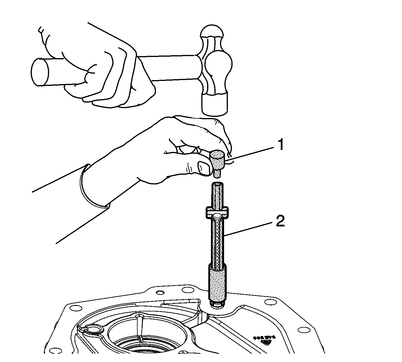
- Place the oil filter assembly with
J 36017 remover
(2) attached onto the clutch housing.
- Using the
J 39442 adapter
(1), tap the oil filter assembly into place with a hammer. Remove the
J 36017 remover
.
Transmission Case Installation
Note: Lubricate all components as the assembly progresses. Use
J 36850 transjel® lubricant
or the equivalent.
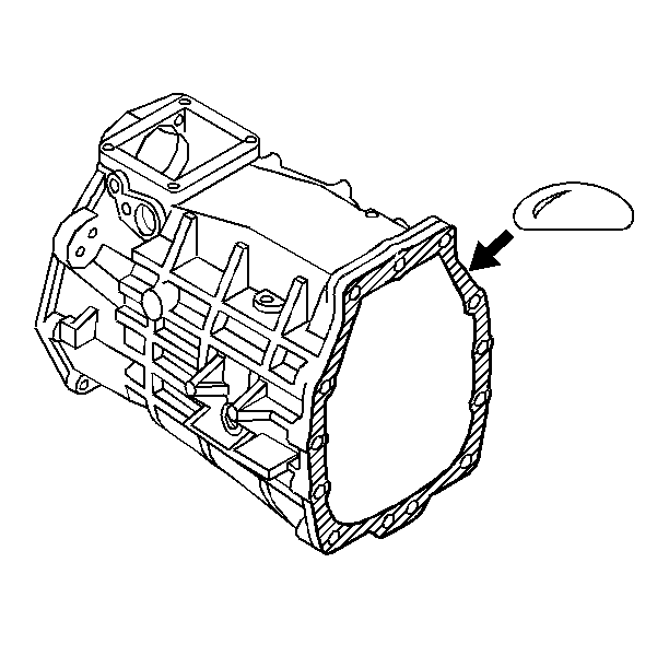
- Apply sealant GM P/N 12345739, (Canadian P/N 10953472) or equivalent to the transmission case to adapter plate mating surface.
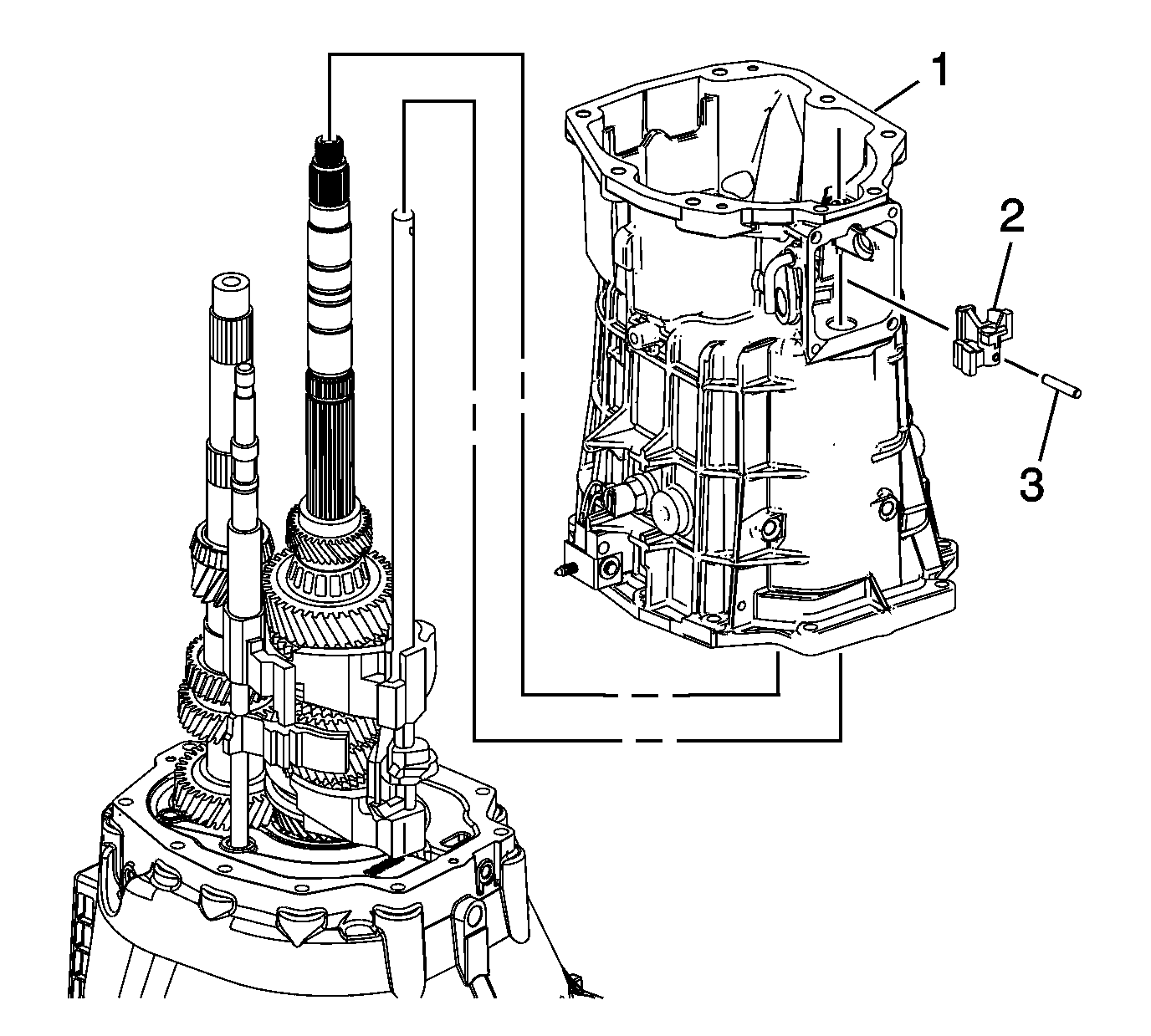
- Do the following in order to install the transmission case and the select control lever assembly:
| 2.1. | Shift the transmission into NEUTRAL in order to keep the 3rd/4th shift shaft from engaging. |
| 2.2. | Install the select control lever assembly (2), through the transmission case opening, while sliding the transmission case (1) onto the gear clusters and the shift rail components. |
| 2.3. | Install the select control lever assembly pin (3). |
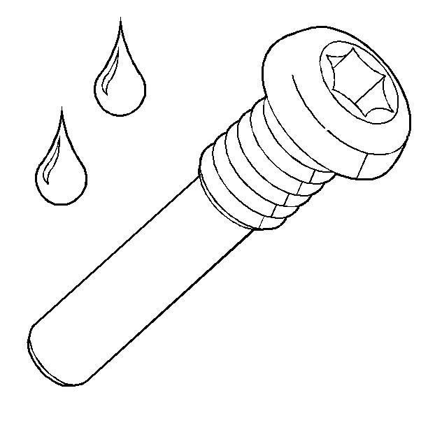
- Apply threadlock GM P/N 12346004, (Canadian P/N 10953480) or equivalent to the threads of the shift lever
guide bolts.
Caution: Refer to Fastener Caution in the Preface section.
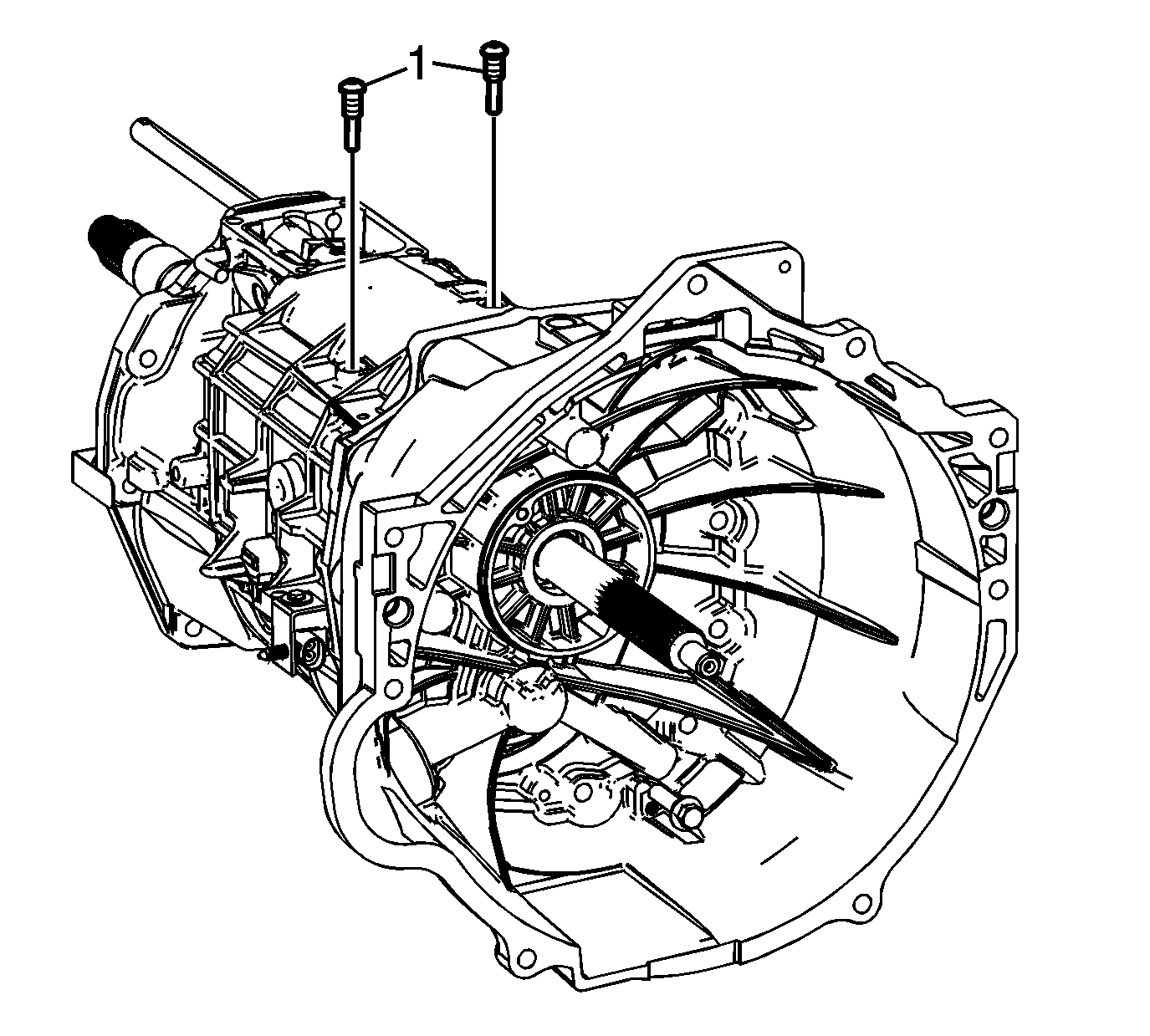
Note: In order to align the shift interlock plate slot with the shift lever guide bolt holes, pull up on the 5th/6th and reverse shift rail assembly while installing the shift lever guide bolts.
- Install the shift lever guide bolts while pulling up on 5th/6th and reverse shift rail assembly. Tighten the bolts to
27 N·m (20 Ib ft).
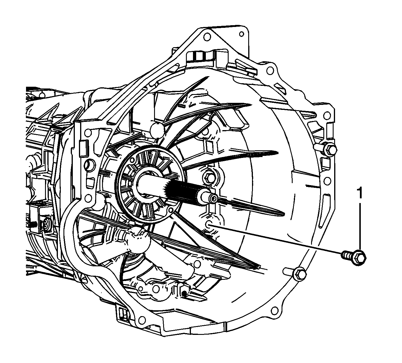
- Install the clutch housing to transmission case bolts
and tighten to
48 N·m (36 Ib ft).
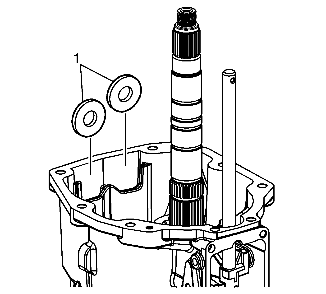
- Install the magnets into the transmission case.
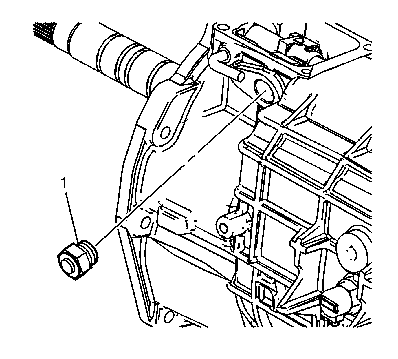
- Install the shift detent assembly and tighten to
40 N·m (30 Ib ft).
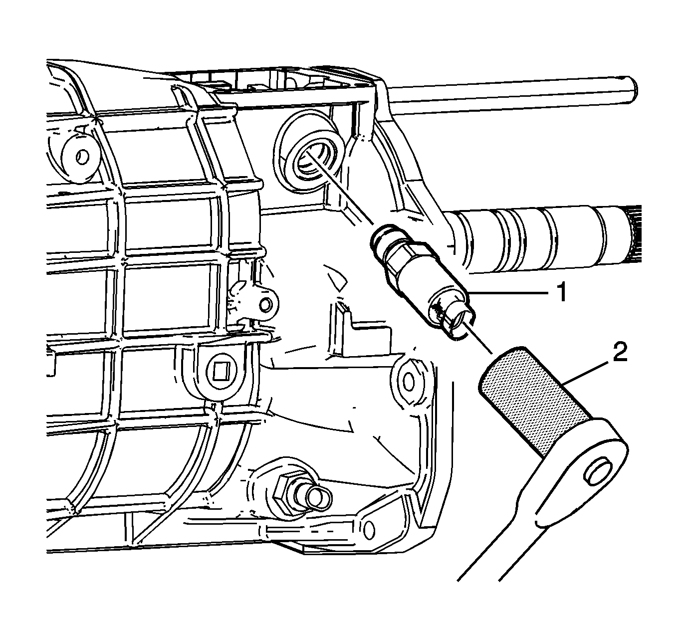
- Using
DT 49293 socket
, install the gear select/skip shift solenoid and tighten to
40 N·m (30 Ib ft).
5th/6th Speed Driven Gear Installation
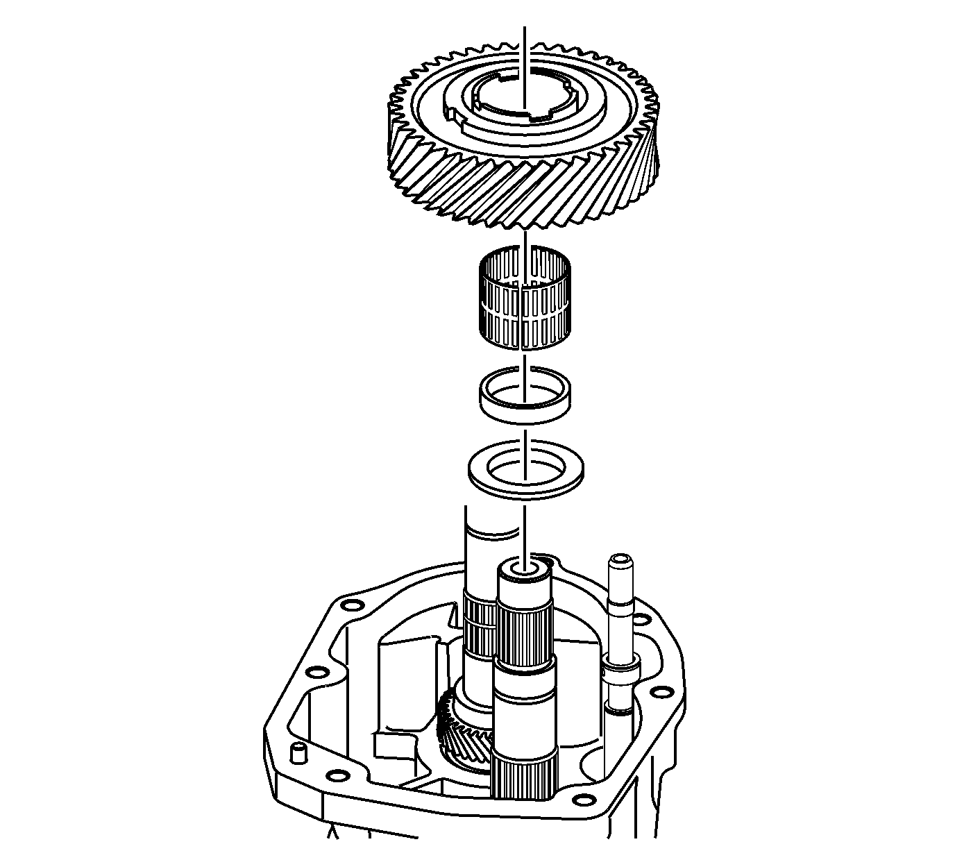
- Install two spacers, caged needle bearing,
and 6th driven gear.
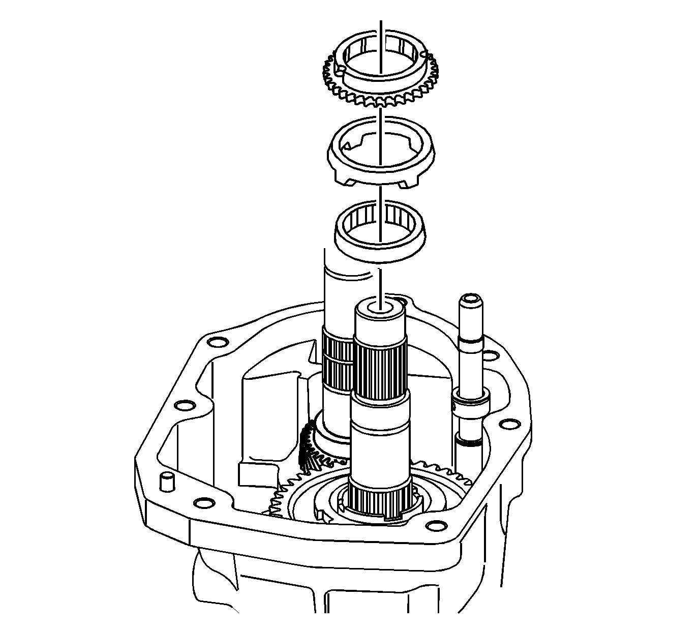
- Install the speed drive gear inner
cone, speed drive gear friction cone, and synchronizer blocking ring.
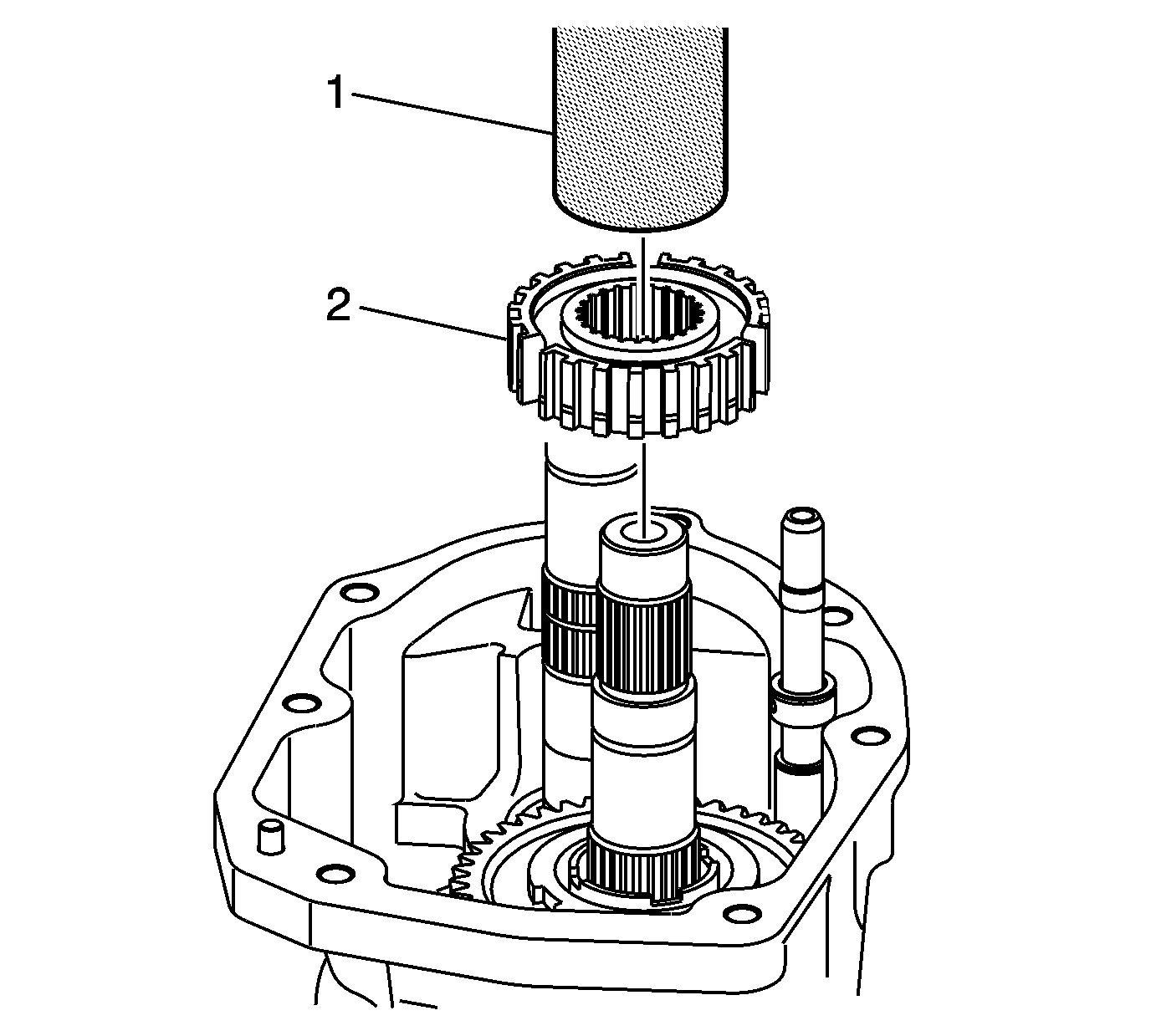
- Install the synchronizer hub assembly (2) using
J 38205-1 tube
(1).
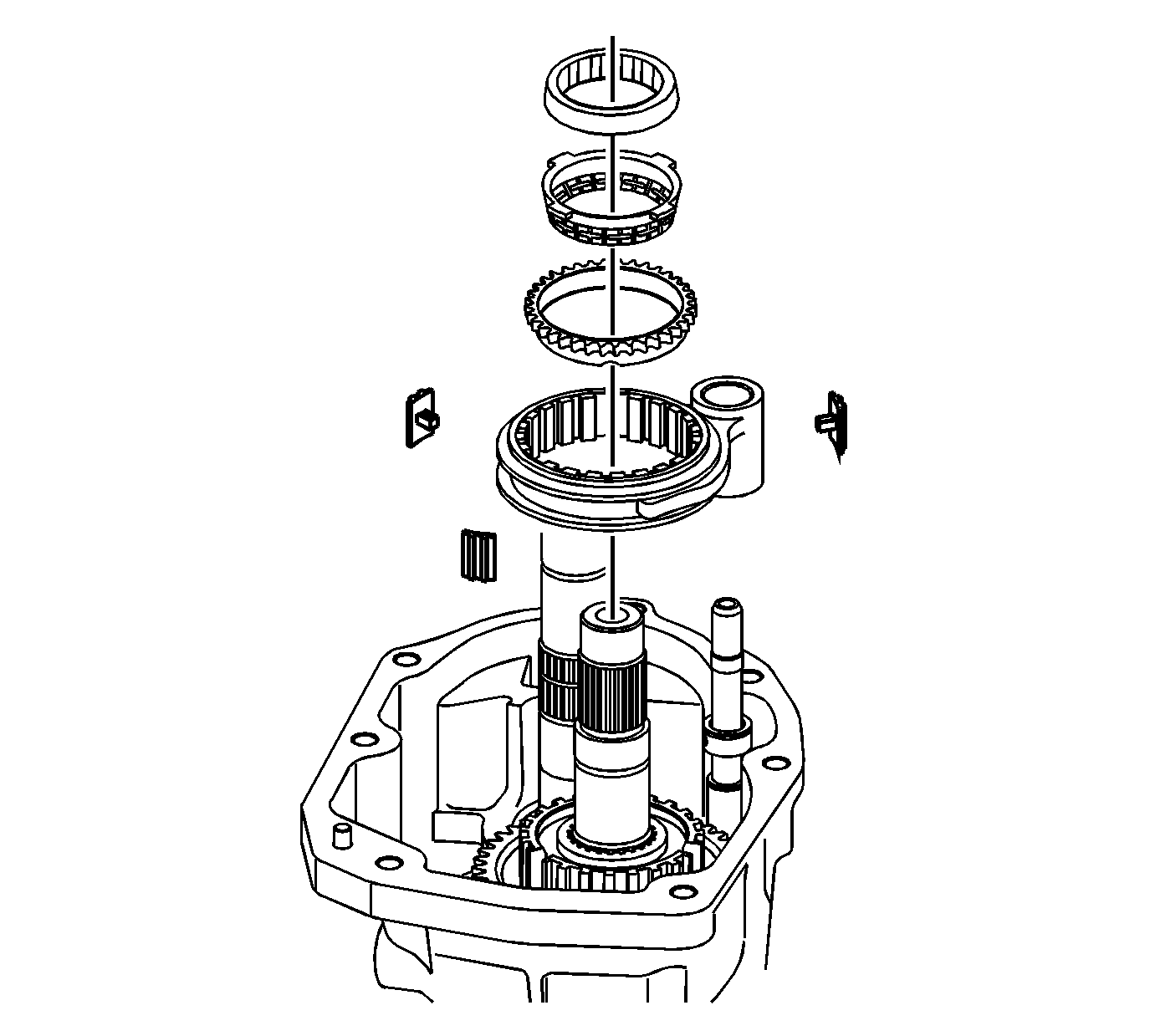
- Install the following components:
| • | drive gear friction cone |
| • | synchronizer blocking ring |
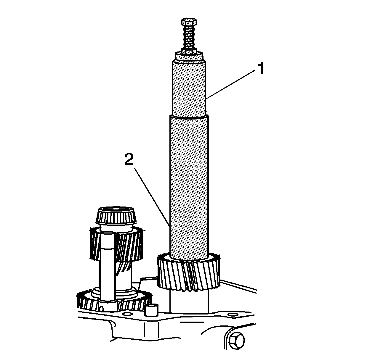
- Install the 5th/6th speed driven gear using the
J 39441-30 installer
(2) and
J 39441-20 adapter
(1). The smaller outside diameter (OD) of the gear faces down.
Reverse Shift Fork Installation
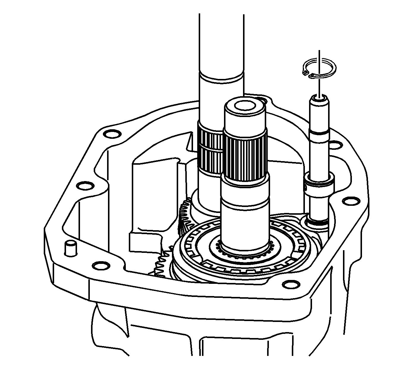
- Install the 5th/6th speed shift fork
retainer ring.
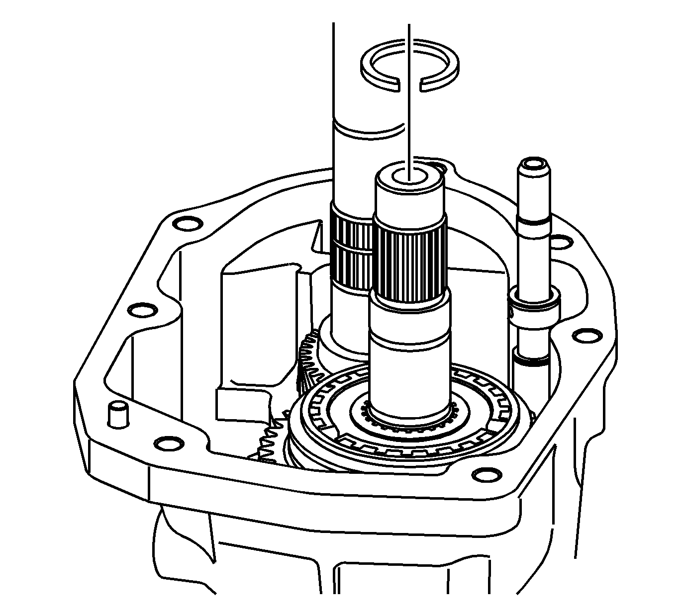
- Install the retainer clip to the countershaft.
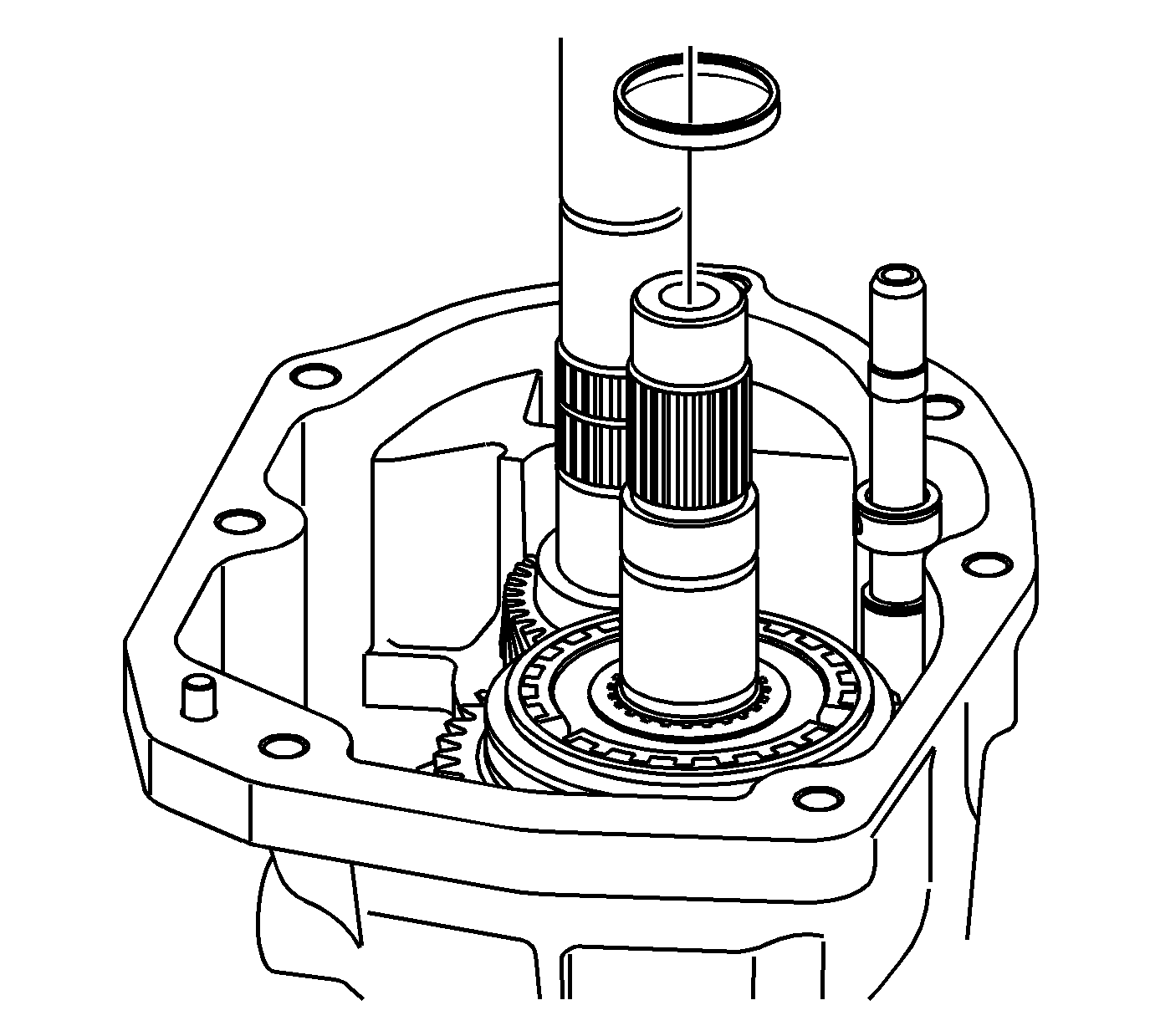
- Install the spacer to the countershaft.
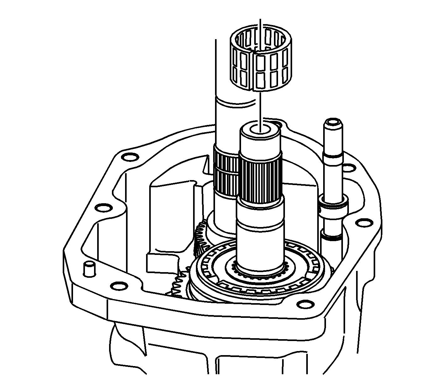
- Install the needle bearing to the countershaft.
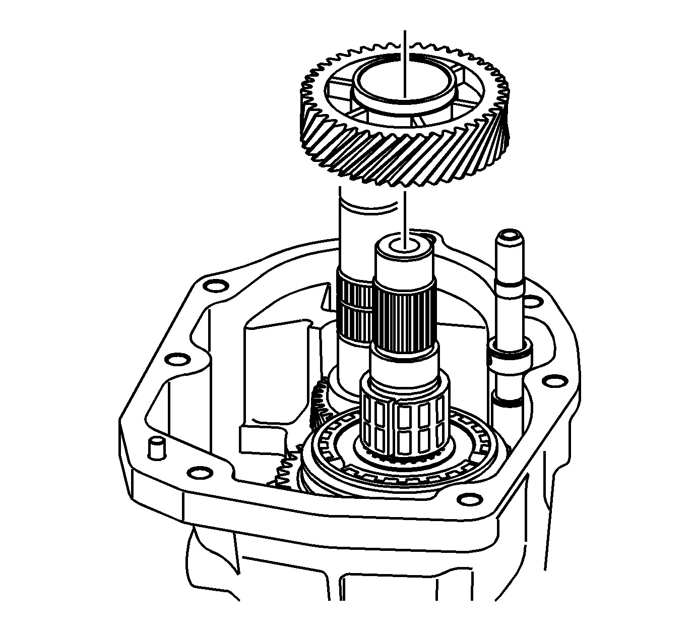
- Install the gear to the countershaft.
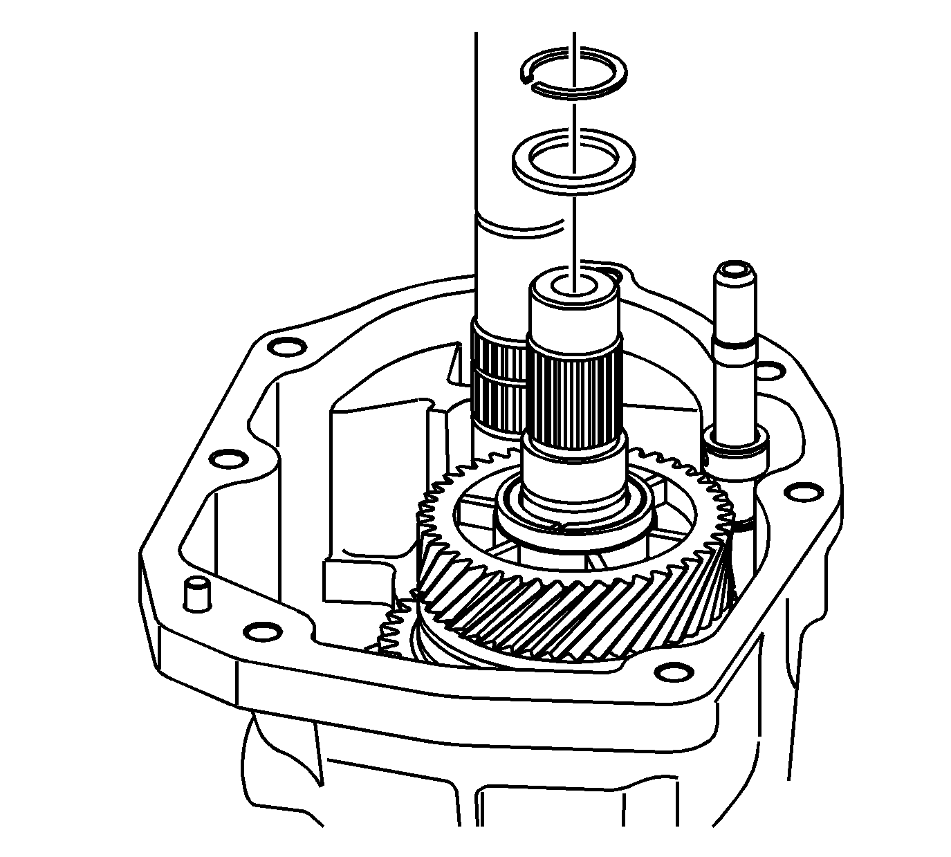
- Install the countershaft retainer and
spacer.
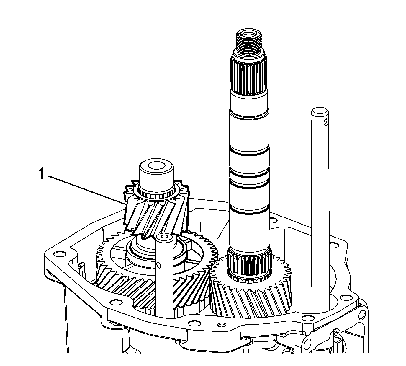
- Install the countershaft gear.
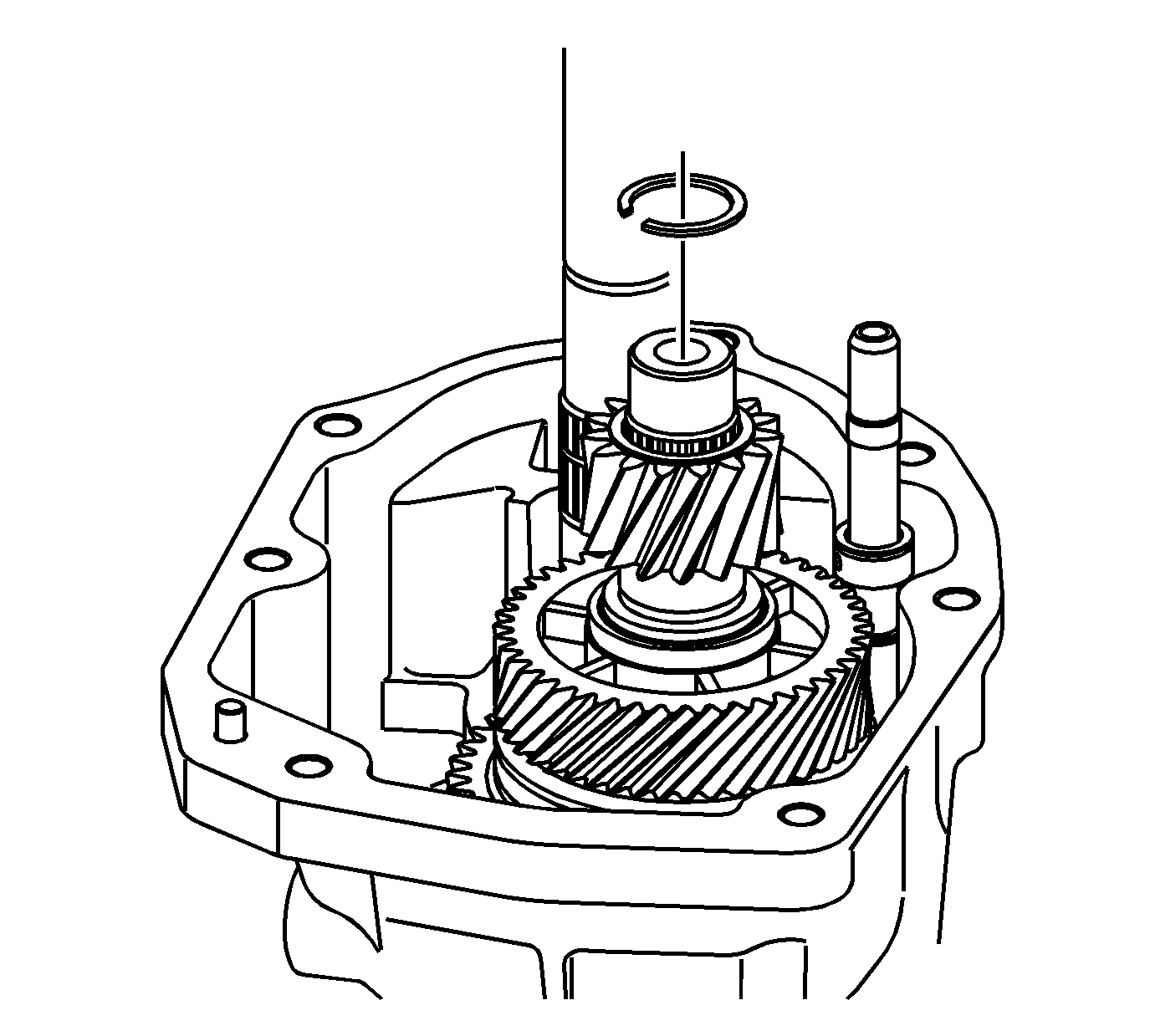
- Install the countershaft retainer ring.
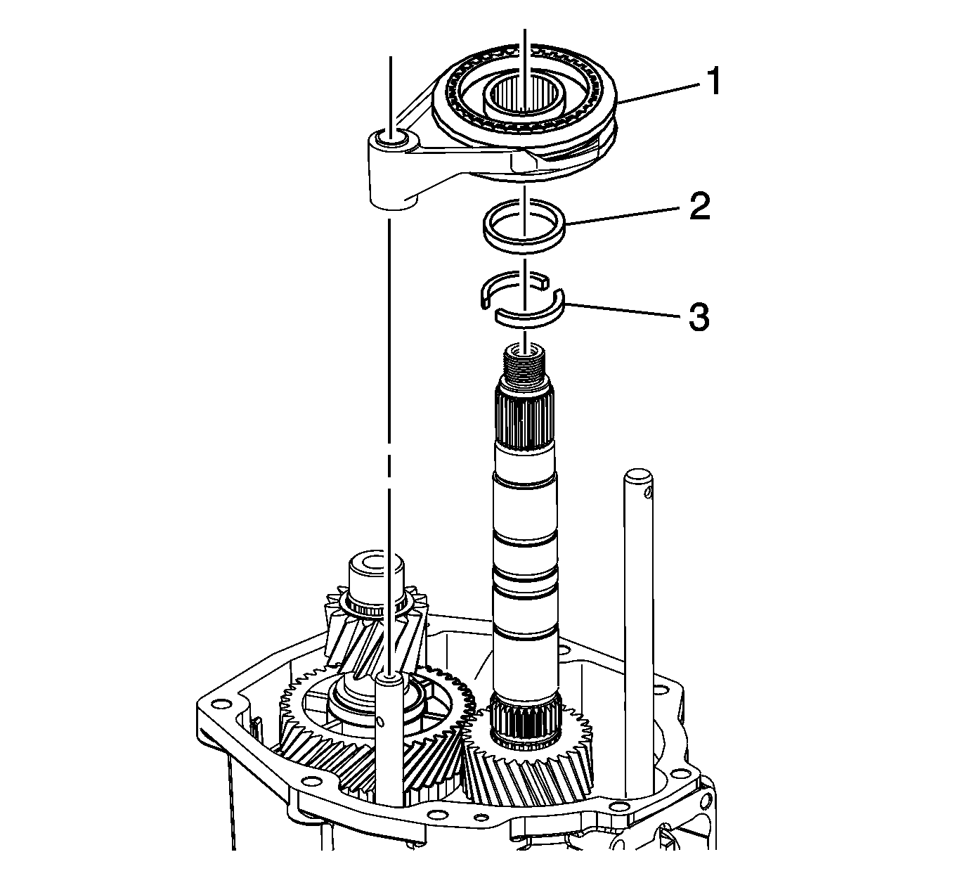
- Install the two piece thrust washer.
- Install the locking ring.
- Install the reverse shift fork and the synchronizer.
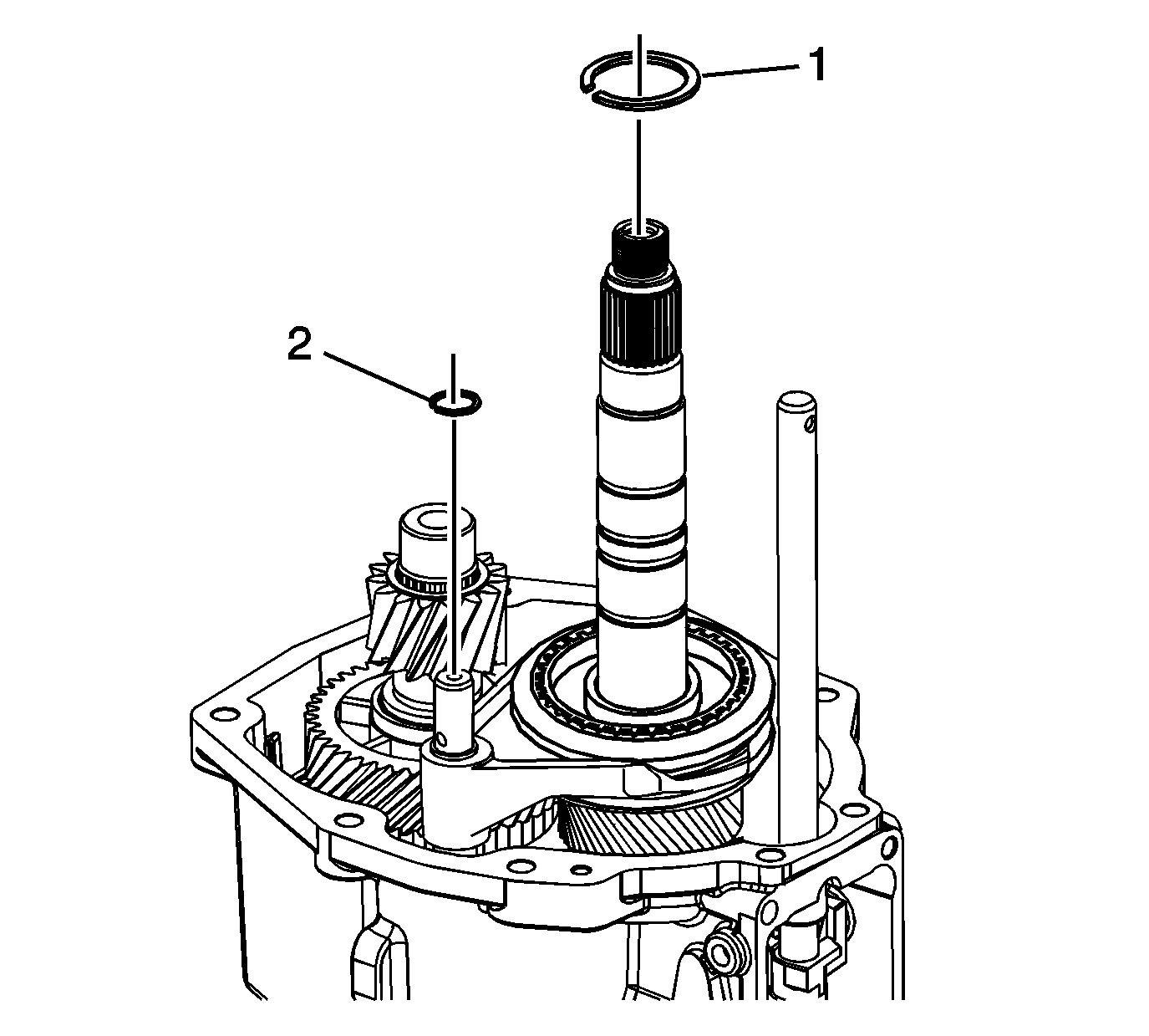
- Install a NEW shift fork retainer ring.
- Install the reverse synchronizer retainer ring.
Reverse Speed Gear Installation
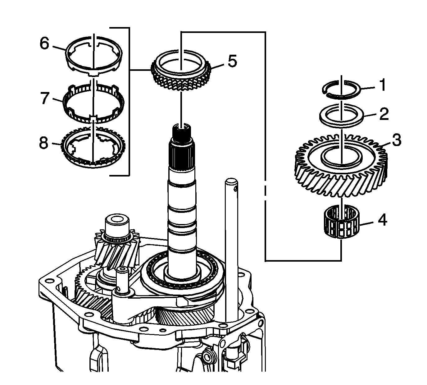
- Install the following parts in order:
| 1.1. | The reverse gear blocking ring assembly (5), including the following components: |
| • | Reverse gear inner ring (6) |
| • | Reverse gear outer ring (7) |
| • | Reverse gear blocking ring (8) |
| 1.2. | The caged needle bearing (4) |
| 1.3. | The reverse speed gear (3) |
| 1.4. | The thrust washer (2) |
| 1.5. | The retainer ring (1) |
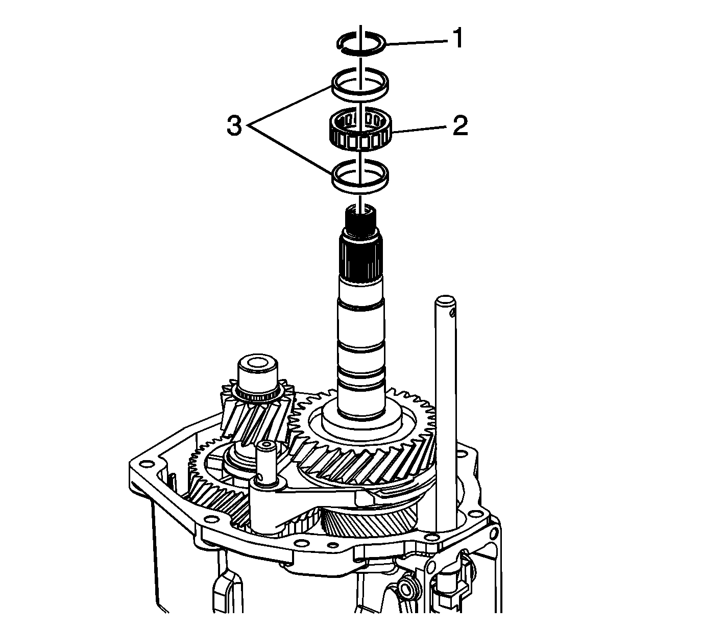
- Install the following parts in order:
| 2.4. | The roller bearing retainer ring |
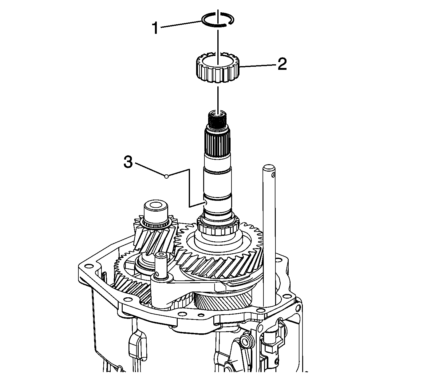
- Install the following parts in order:
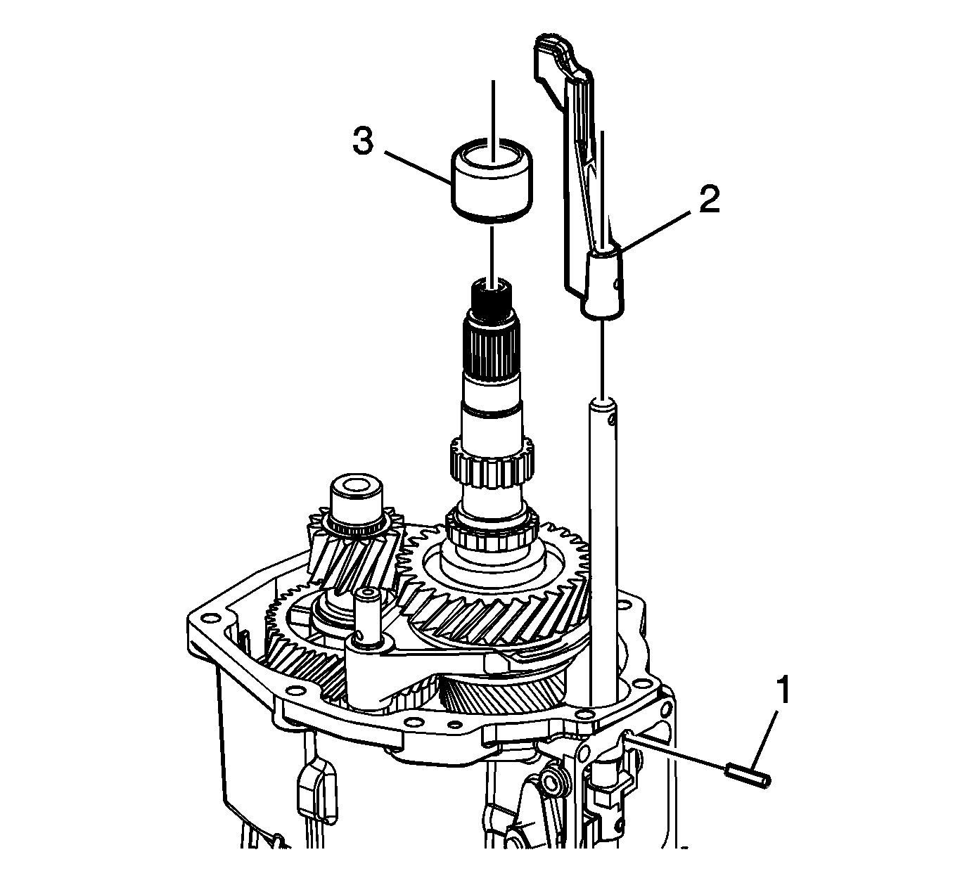
- Install the extension housing main shaft bearing race.
- Install the shift shaft extension.
- Install NEW shift guide roll pin.
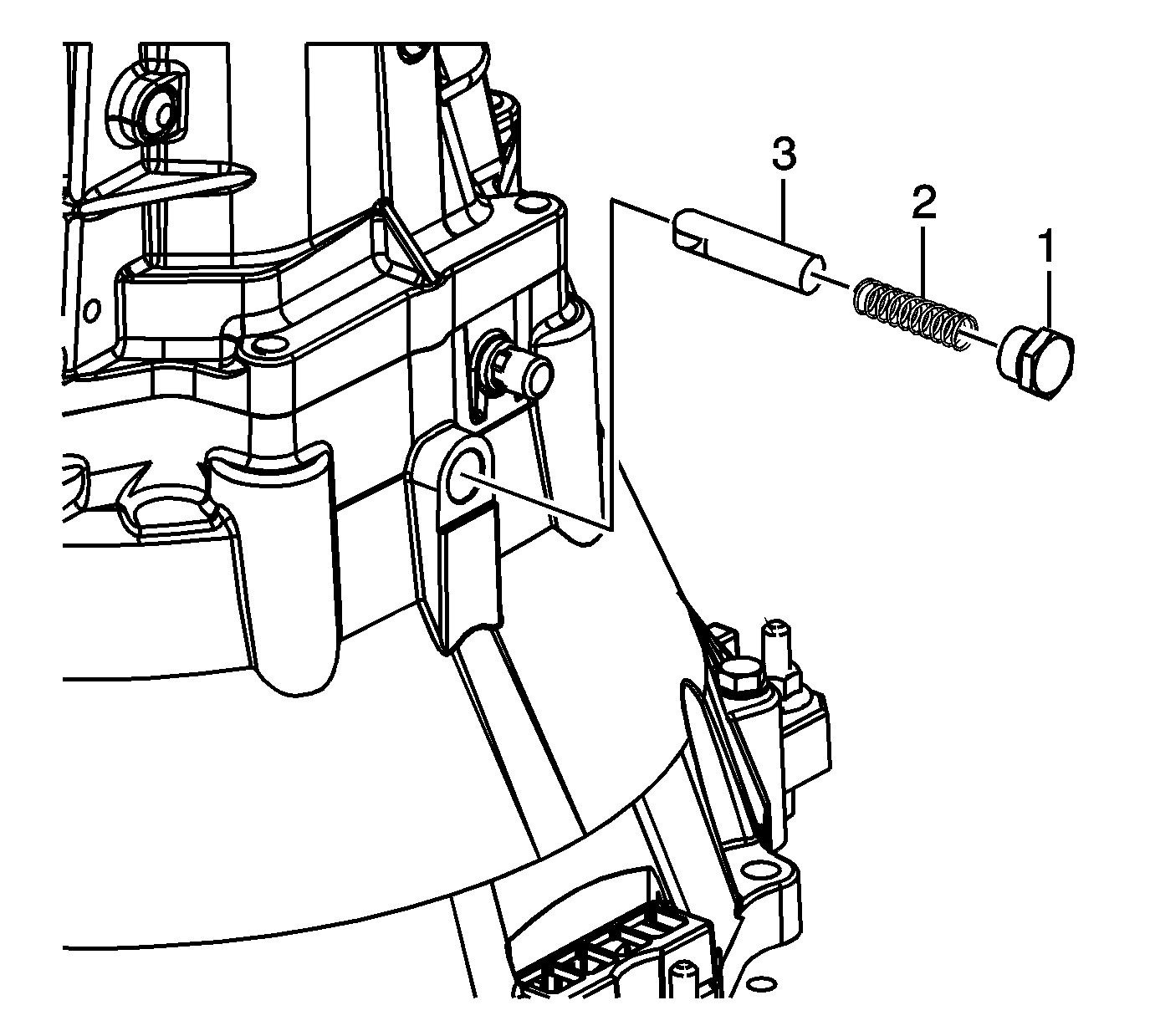
- Lift up on the shift shaft extension while installing the shift detent roller,
spring and plug. Tighten the plug to
24 N·m (18 lb in).
Extension Housing Assembly Installation
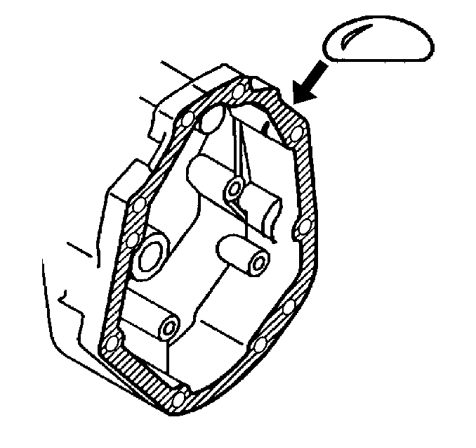
- Apply sealant GM P/N 12345739, (Canadian P/N 10953472) or equivalent to the extension
housing to the transmission case mating surface.
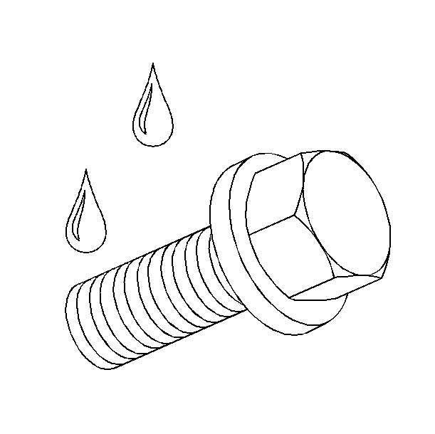
- Apply thread sealer GM P/N 12346004, (Canadian P/N 10953480) or equivalent to the top 2 extension
housing bolts.
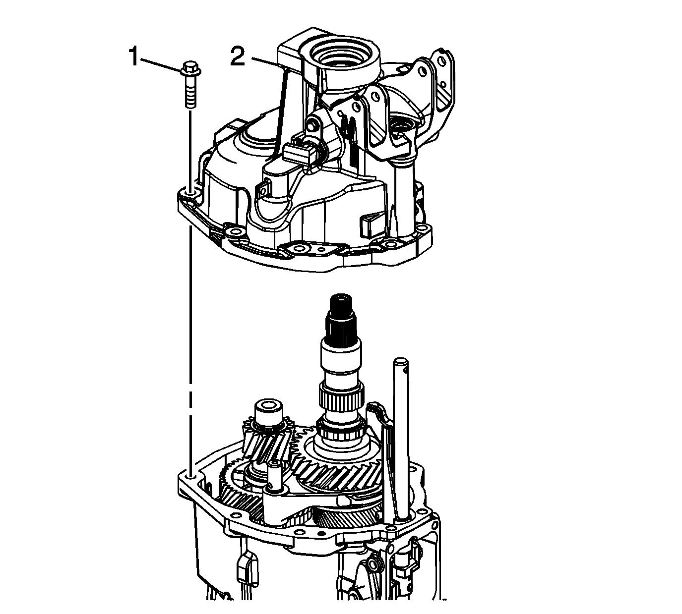
Note: Align the 5th/6th shift shaft to the extension housing bore in order to install the extension housing.
- Install the extension housing.
- Install the extension housing bolts and tighten to
48 N·m (36 lb ft).
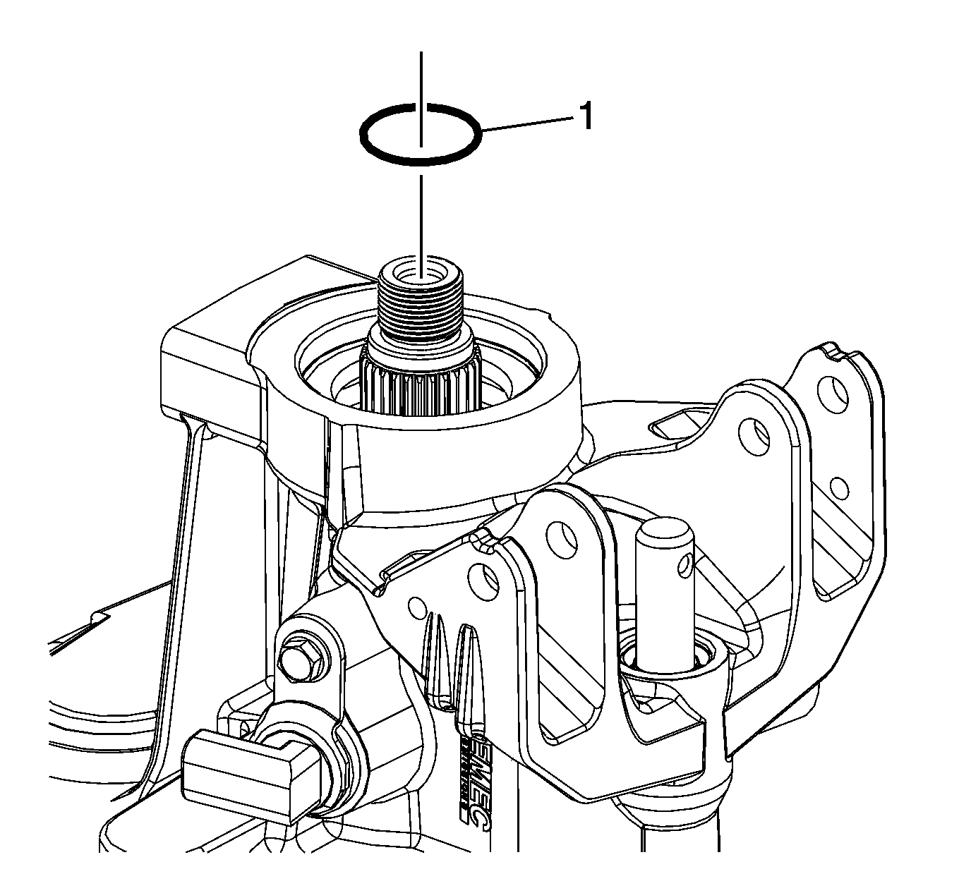
- Install the propshaft O-ring (1).
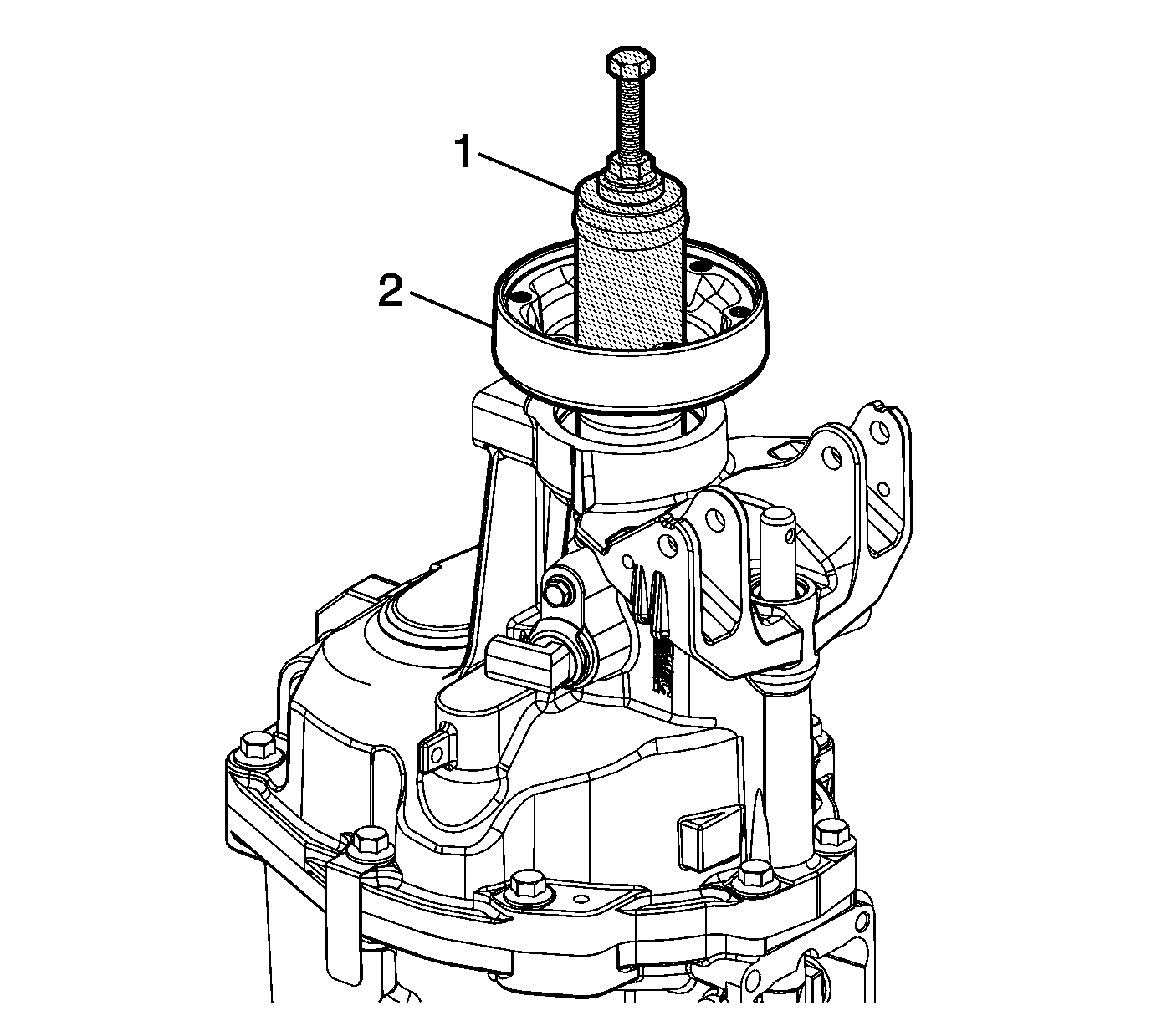
- Install the propshaft transmission yoke (2). Install
J 39441-30 installer
(1) onto the transmission yoke. Turn the bolt to install the transmission
yoke into the mainshaft.
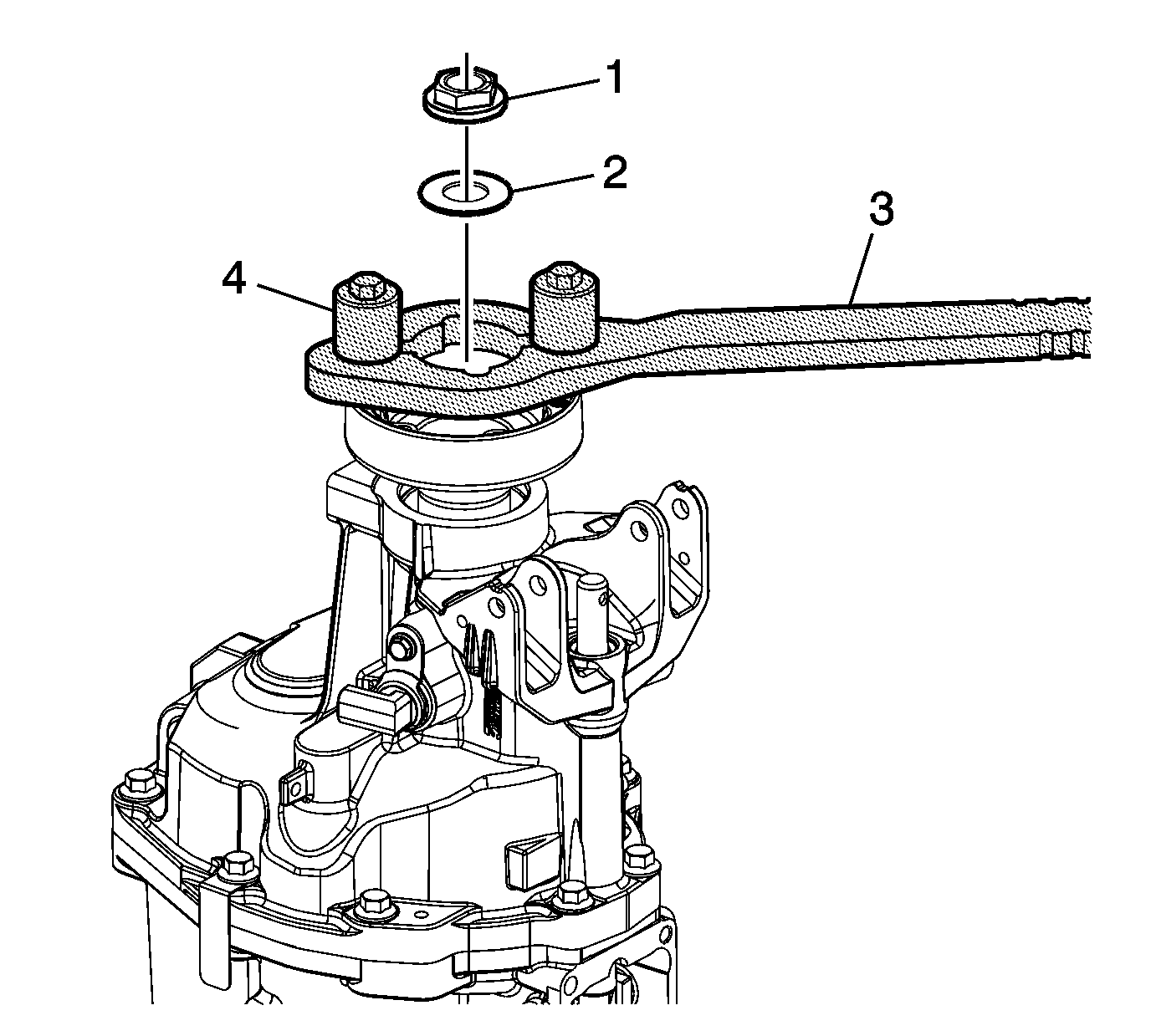
- Install the propshaft washer (2) and nut (1).
- Use the
J 08614A holder
(3) and
J 08614-20 bolts
(4) to hold the propshaft transmission yoke.
Tighten the nut (1) to
136 N·m (100 lb ft)
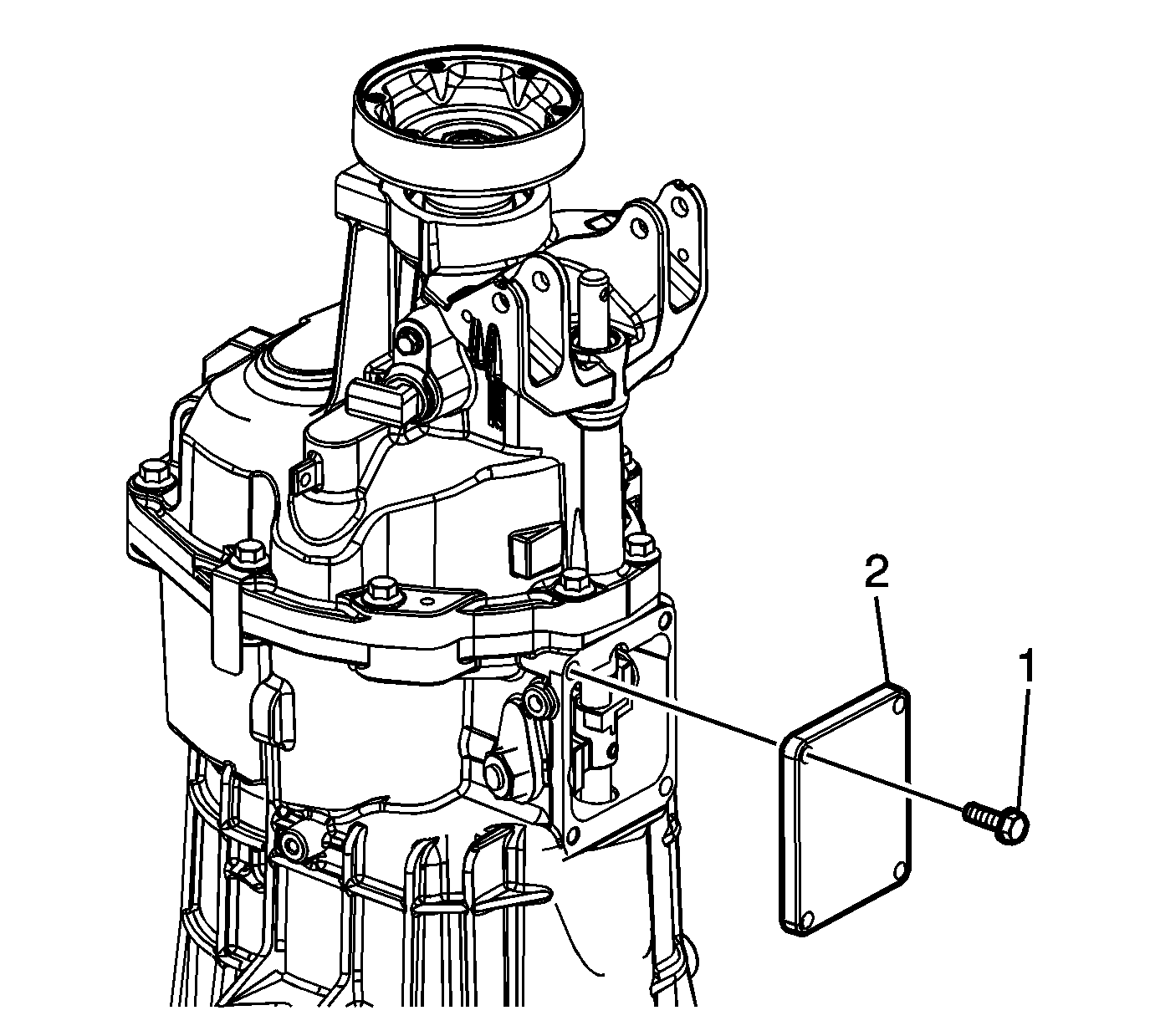
- Install the shifter cover plate.
- Install the shifter cover plate bolts and tighten to
20 N·m (15 lb ft).
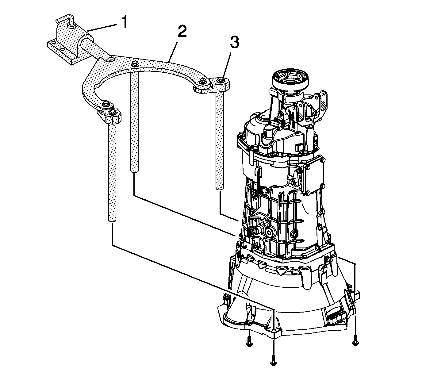
- Remove the
DT 47678 flange
(2) and
DT 47678-10 adapter
.
- Remove the
DT 47678 flange
and
DT 47678-10 adapter
from
J 3289-20 fixture
(1).


