For 1990-2009 cars only
Special Tools
| • | J 28537-17 Bearing Race Installer |
| • | J 36183 Press Tube |
| • | J 36184 Press Tube Adapter |
| • | J 39371 1st/2nd Synchronizer Installer |
| • | J 39441 5th/6th Driven Gear Installer |
| • | J 39441-10 Installer Adapter |
| • | J 39441-20 5th Gear Installer Adapter |
| • | J 39473 Mainshaft Bearing Installers . |
| • | J 44735 Installation Tube |
For equivalent regional tools, refer to Special Tools
Mainshaft
- Install the 3rd speed gear caged needle bearing and the spacer.
- Install the 3rd speed drive gear spacer.
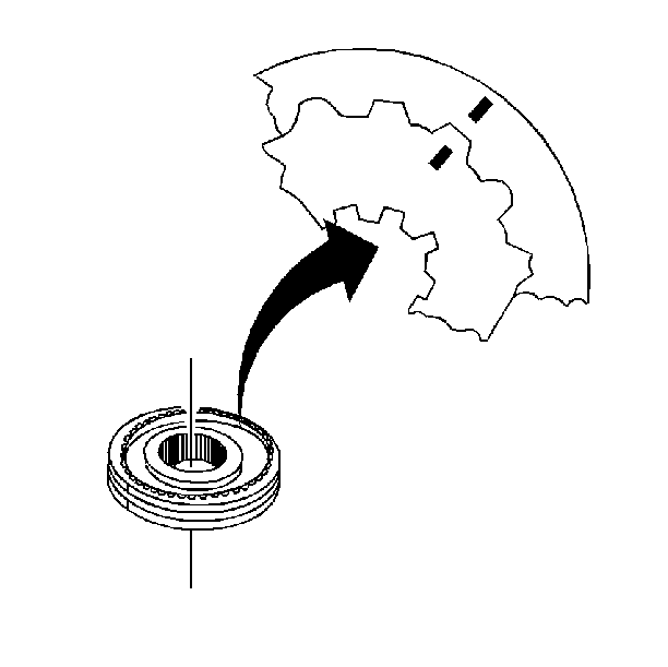
- Check the 3rd/4th speed gear synchronizer assembly scribe marks for correct positions.
- Install the 3rd/4th synchronizer assembly as follows:
- Install the following parts in order:
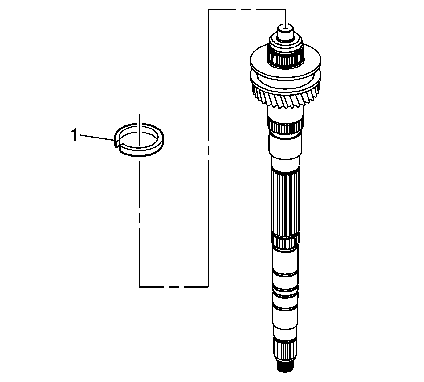
- Install the 3rd/4th synchronizer retainer ring (1).
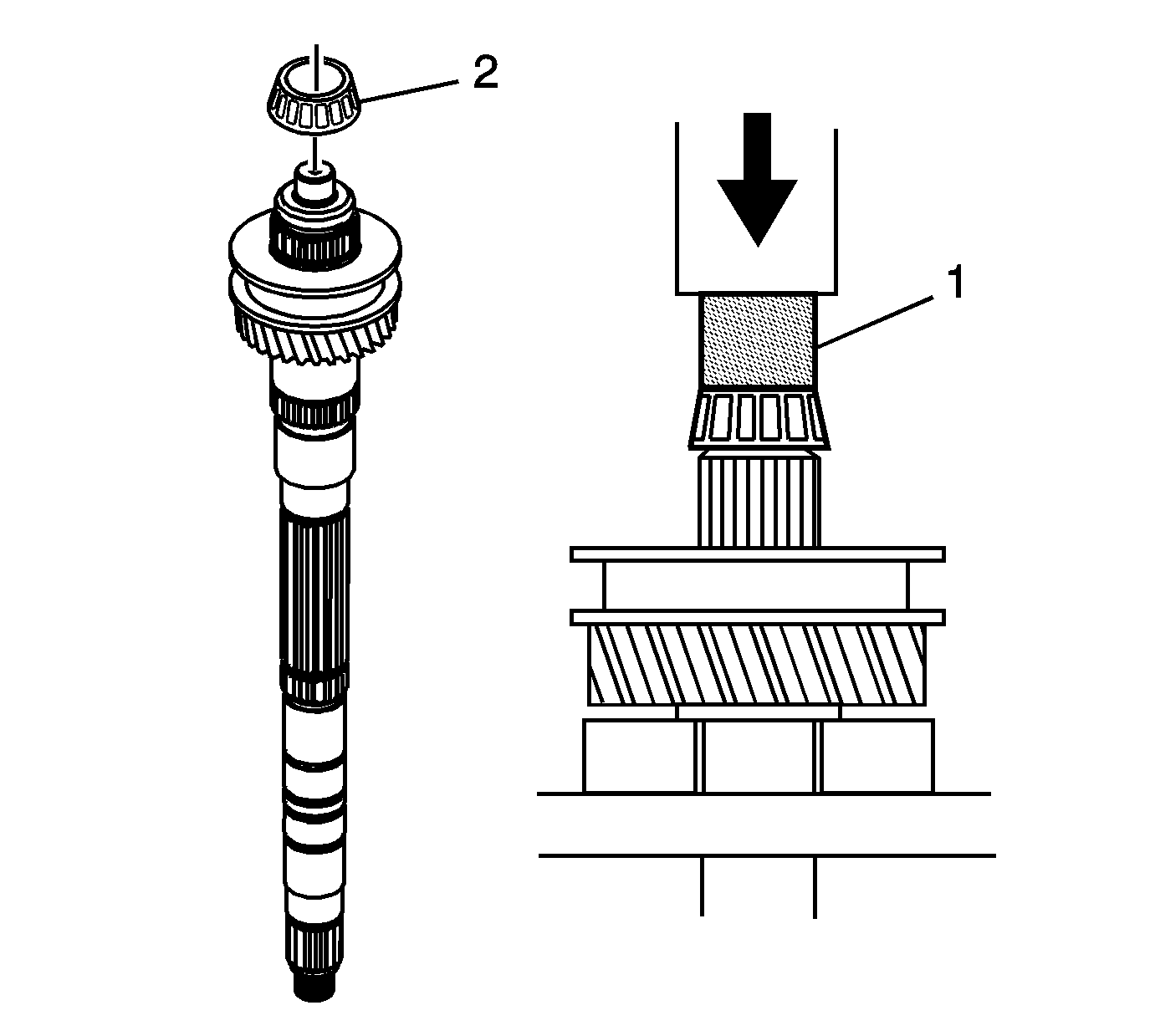
- Install a new mainshaft small tapered bearing (2), using the J 39473 installers (1), V-blocks, and a hydraulic press.
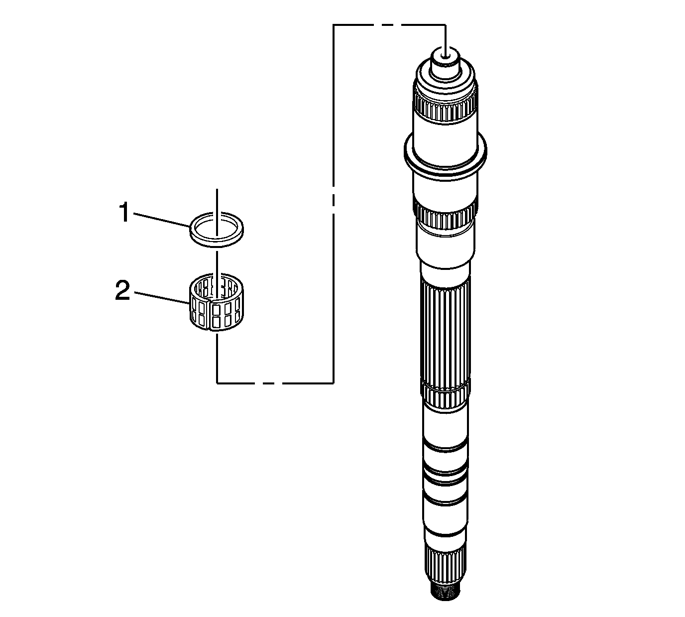
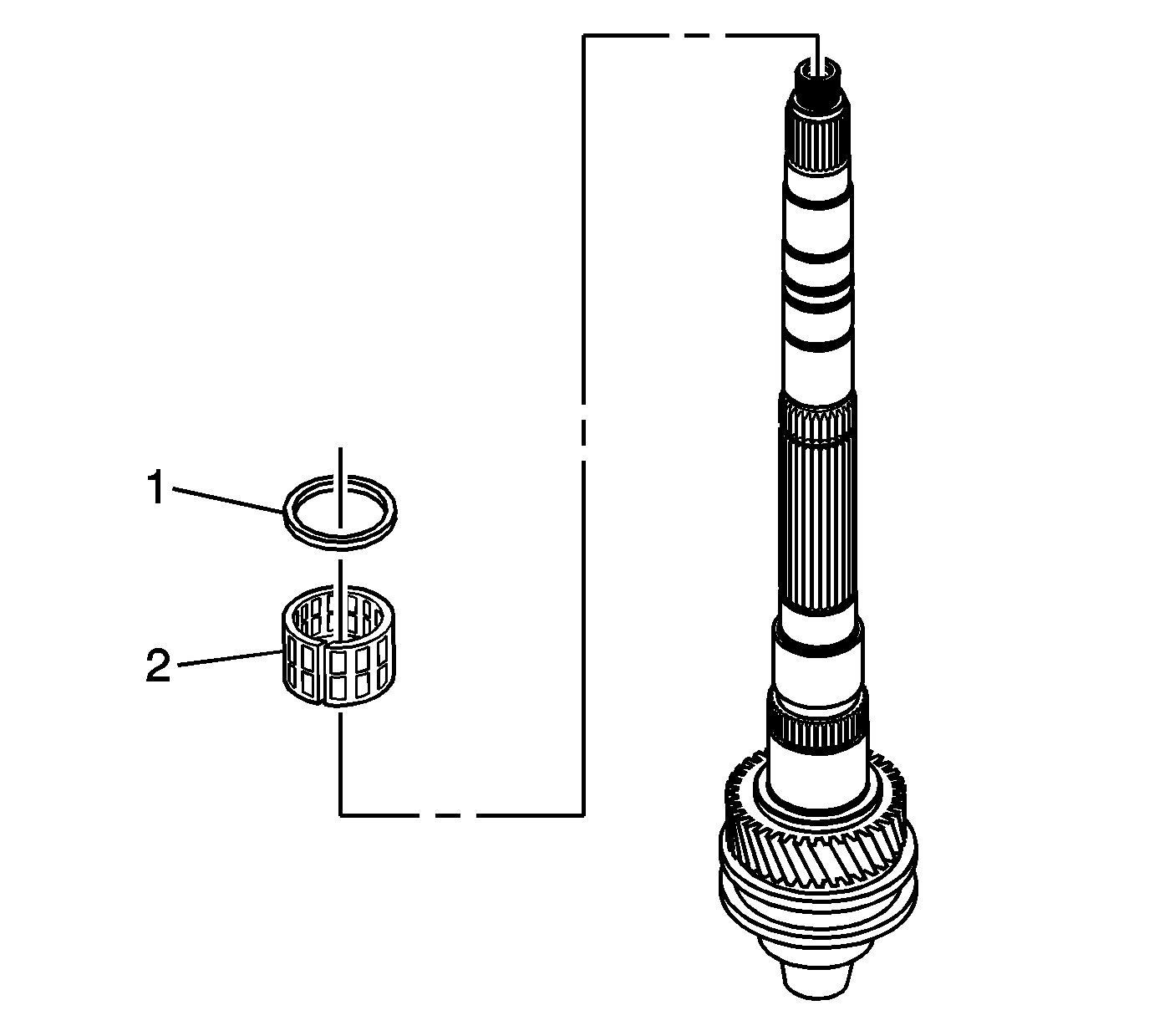
- Install the 2nd speed gear caged needle bearing (2) and bearing spacer (1).
- Do the following when installing the 1st/2nd synchronizer assembly:
- Install the following parts in order using the J 39371 1st/2nd installer and a hydraulic press:
- Install the following parts in order:
- Install the following parts in order:
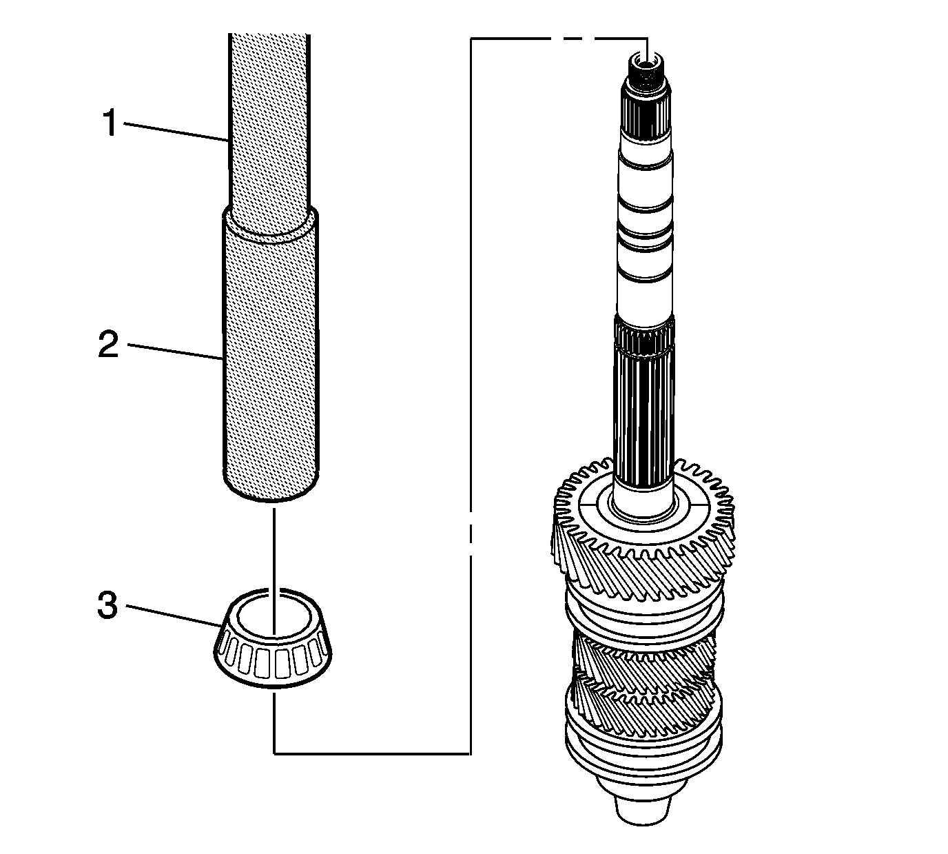
- Using J 39441 installer (1), J 39441-20 adapter (2), and a press, install the mainshaft large tapered bearing (3).
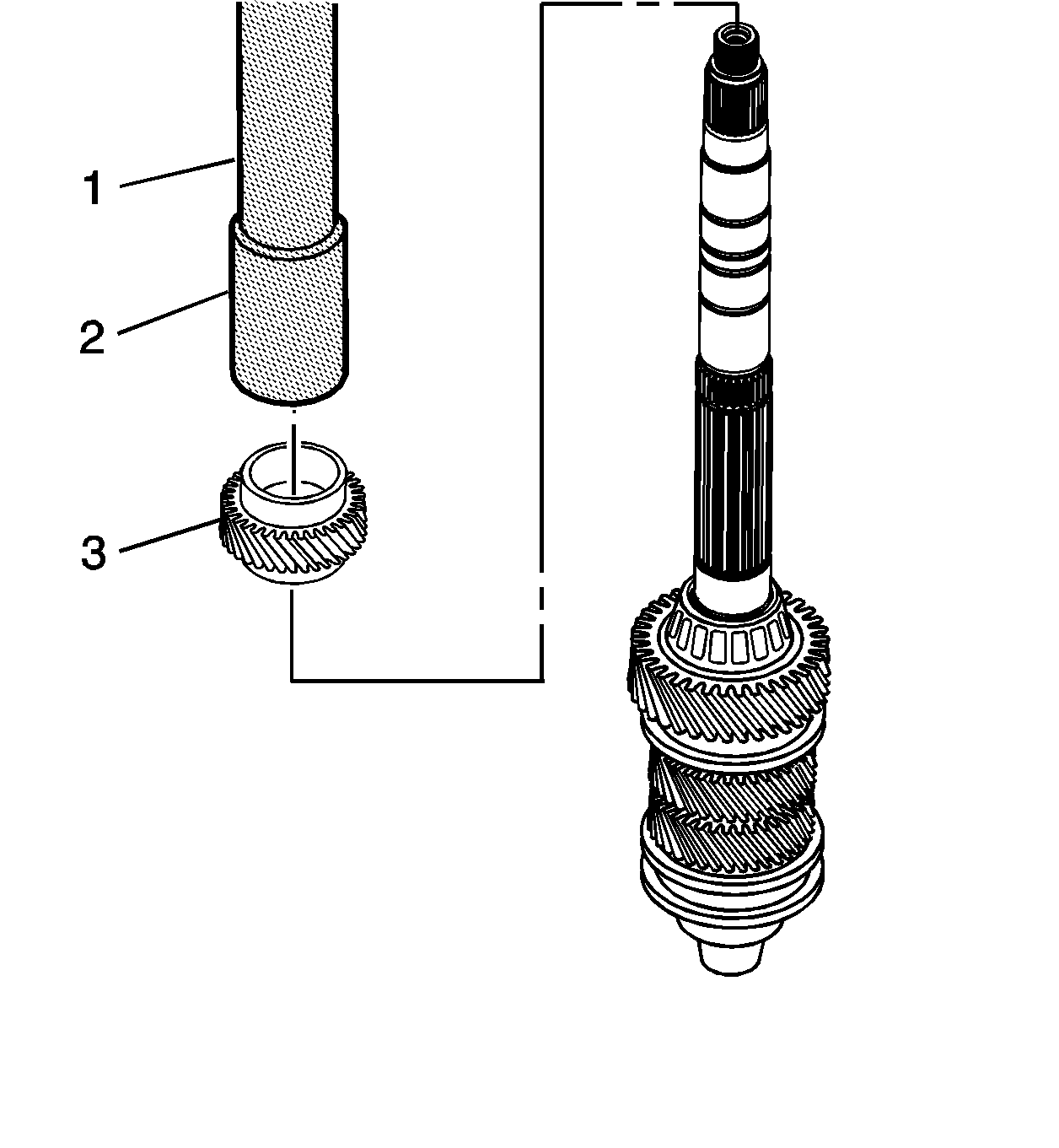
- Using the J 39441 gear installer (1) and the J 39441-10 adapter (2), install the 6th speed driven gear (3).
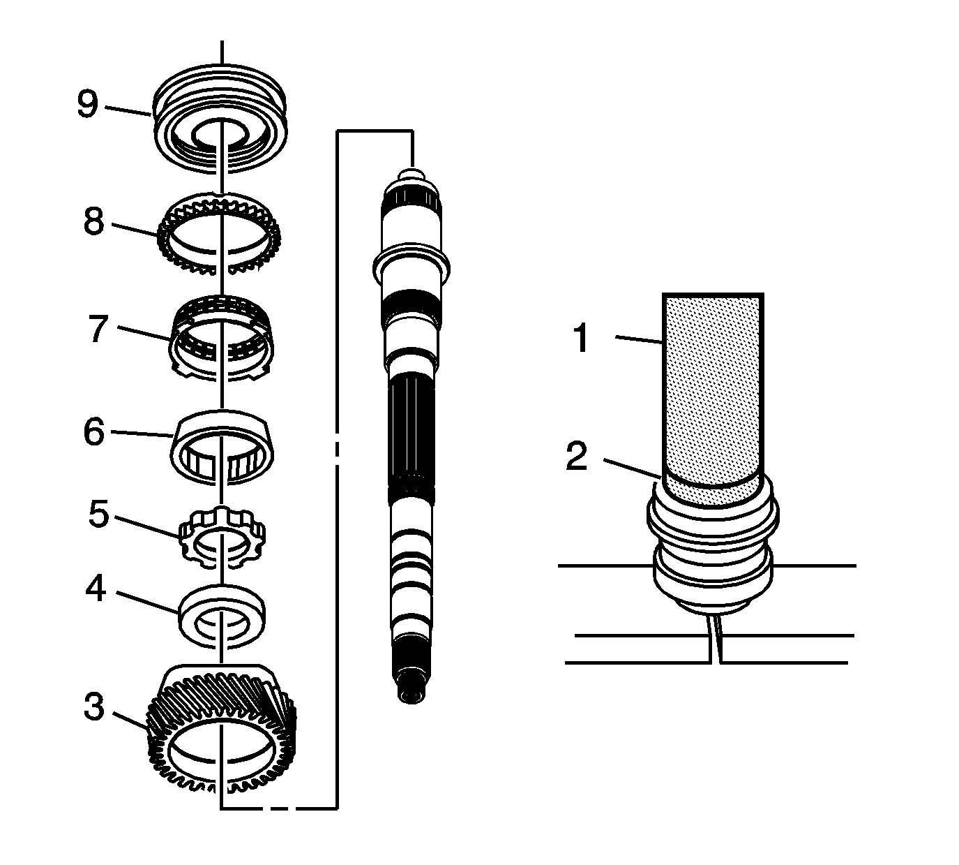
| 4.1. | Start the press operation. |
| 4.2. | STOP pressing before the keys engage the blocking ring slots. |
| 4.3. | Lift and rotate the 3rd speed gear in order to engage the keys with the blocking ring. |
| 4.4. | Continue pressing until the synchronizer is seated. |
| 5.1. | The 3rd speed gear (3) |
| 5.2. | The spacer (4) |
| 5.3. | The thrust washer (5) |
| 5.4. | The 3rd speed gear inner cone (6) |
| 5.5. | The 3rd speed gear friction cone (7) |
| 5.6. | The 3rd speed gear blocking ring (8) |
| 5.7. | The 3rd/4th speed gear synchronizer assembly (9). The groove on the sleeve faces the 3rd speed gear. |
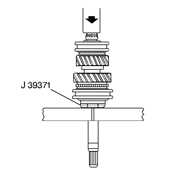
| 9.1. | Start the press operation. |
| 9.2. | Stop pressing before the keys engage the blocking ring slots. |
| 9.3. | Lift and rotate the 2nd speed gear in order to engage the keys with the blocking ring. |
| 9.4. | Continue pressing until the synchronizer is seated. |
| 10.1. | The 2nd speed gear |
| 10.2. | The 2nd speed gear inner cone |
| 10.3. | The 2nd speed gear friction cone |
| 10.4. | The 2nd speed gear blocking ring |
| 10.5. | The 1st/2nd synchronizer assembly (The ID groove on the sleeve faces the 1st speed gear.) |
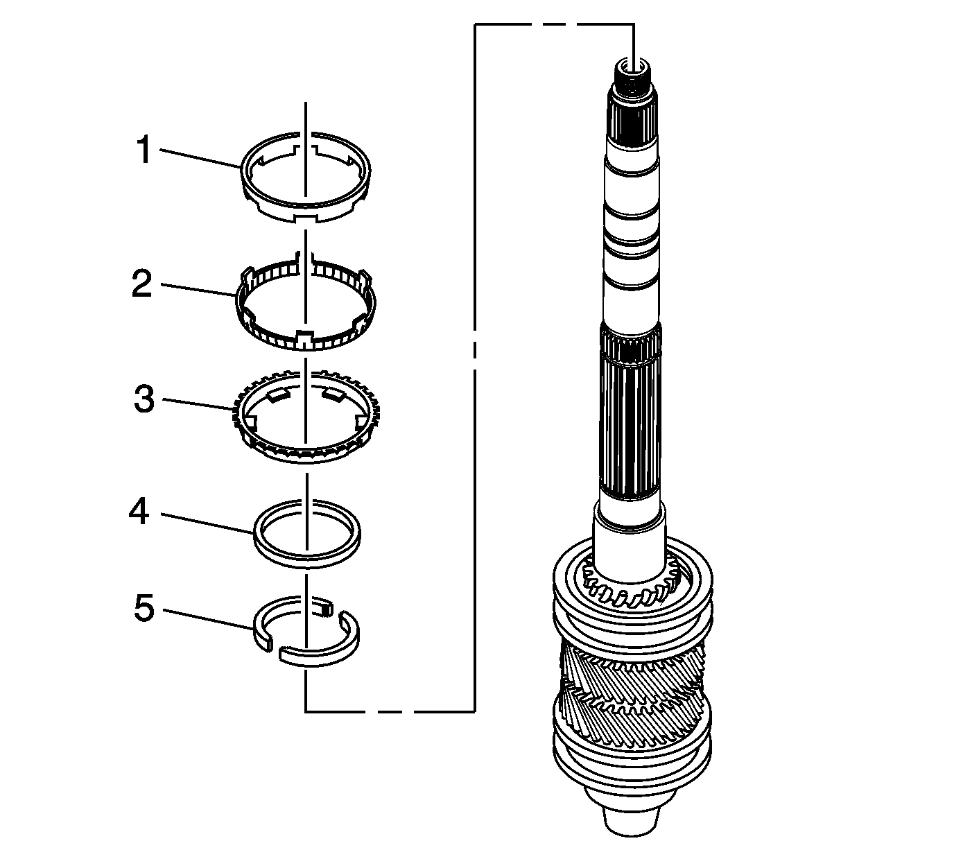
| 11.1. | The 1st speed gear two piece washer (5) |
| 11.2. | The 1st speed gear locking ring (4) |
| 11.3. | The 1st speed gear synchronizer blocking ring (3) |
| 11.4. | The 1st speed gear outer cone (2) |
| 11.5. | The 1st speed gear inner cone (1) |
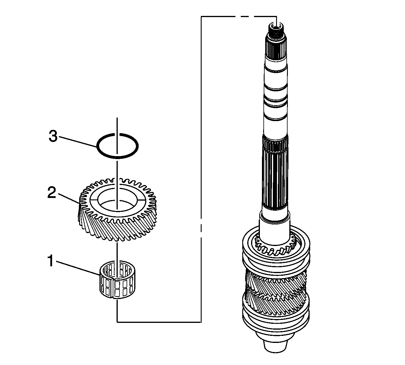
| 12.1. | The 1st speed gear caged needle bearing (1) |
| 12.2. | The 1st speed gear (2) |
| 12.3. | The mainshaft inner seal O-ring (3) |
Input Shaft
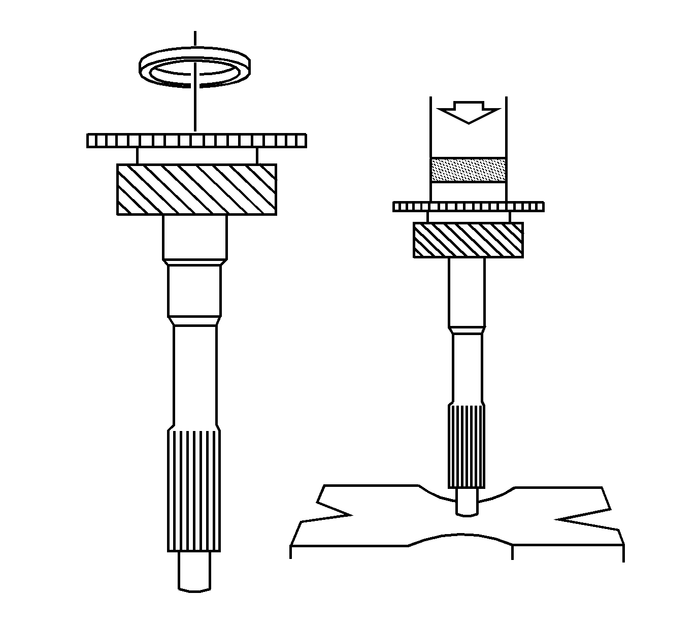
- Install a new bearing race on the input shaft, using the J 28537-17 installer and a hydraulic press.
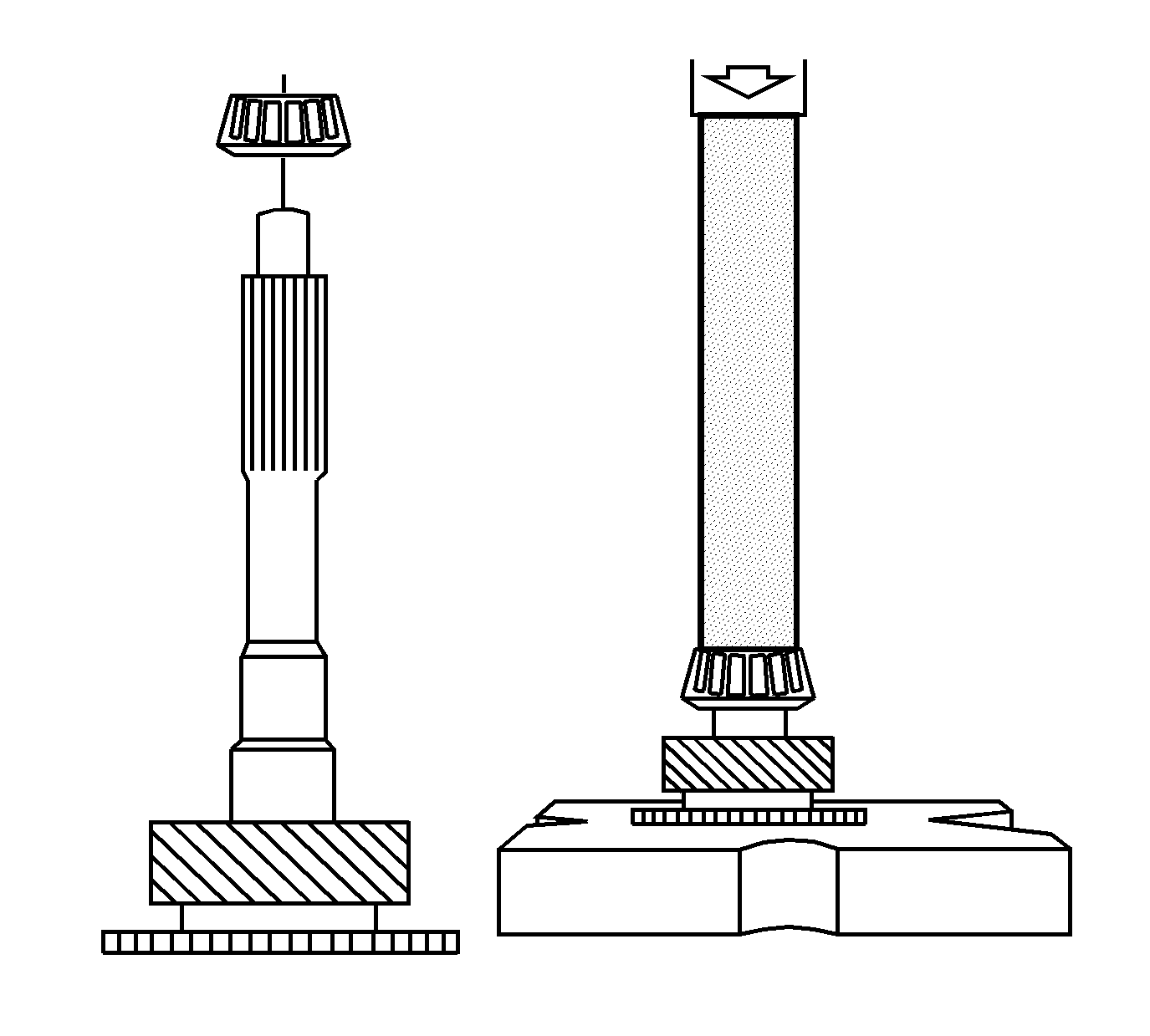
- Install a new tapered bearing on the input shaft. Use the J 44735 tube and a hydraulic press.
