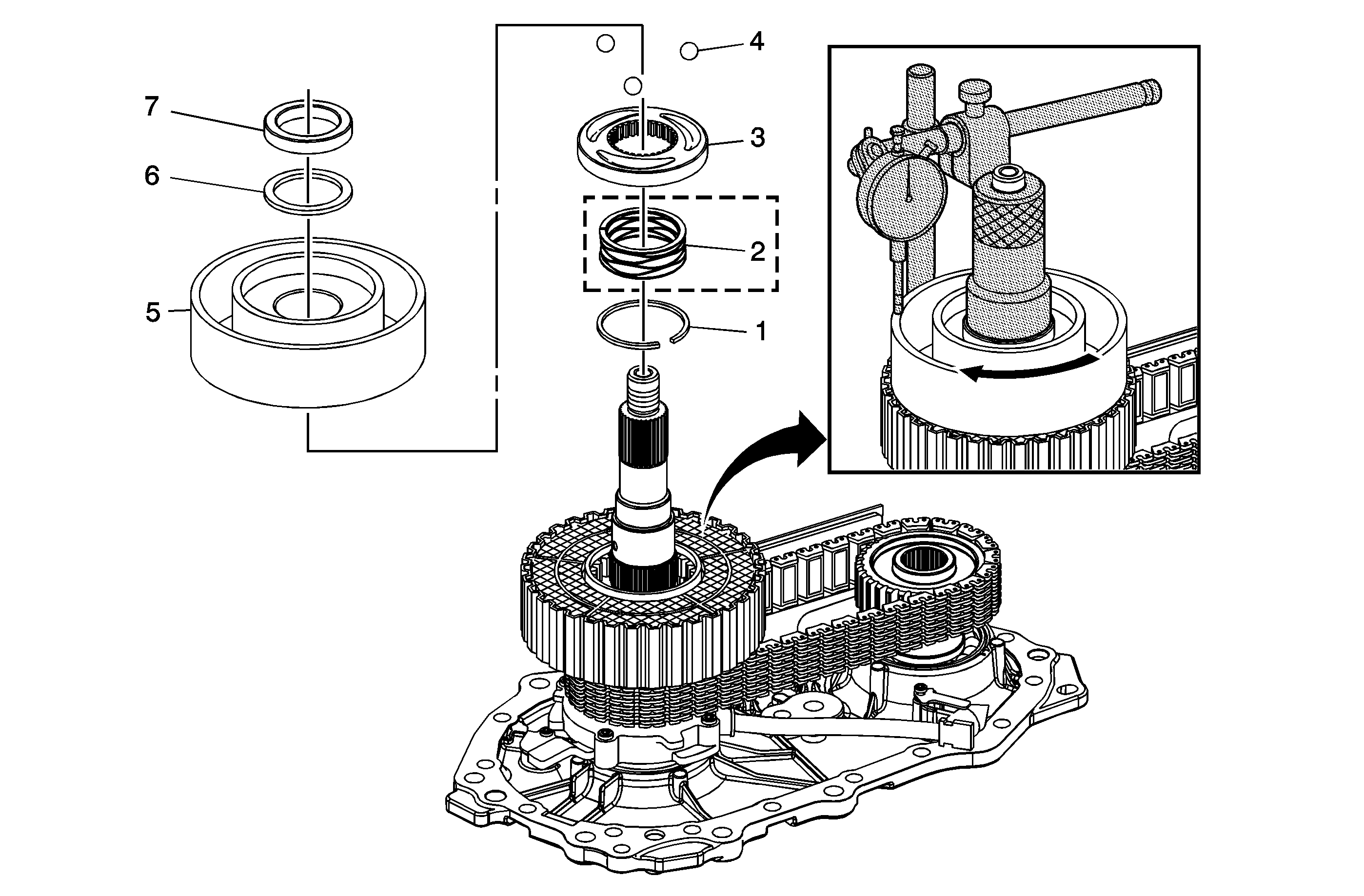
Callout
| Component Name
|
Preliminary Procedures
- The purpose of this procedure is to obtain a proper clutch travel of 0.7-1.2 mm (0.0275-0.0472 in.) when assembled with a selective thrust washer.
- Assemble or disassemble the internal components to the clutch pack snap ring (1). Refer to
Transfer Case Assemble Transfer Case Cover, Apply Cam, and Clutch Pack Installation.
|
1
| Transfer Case Snap Ring
|
2
| Transfer Case Wave Spring
Tip
Temporarily remove the spring (2) for selective thrust washer measurement. |
3
| Transfer Case Apply Cam
|
4
| Transfer Case Balls
|
5
| Transfer Case Rotor Assembly
|
6
| Transfer Case Thrust Bearing
|
7
| Transfer Case Selective Thrust Washer
Procedure
- Attach, screw, the
DT-48553
to the input shaft until hand tight.
- Attach the
J 8001
.
- Zero the
J 8001
on the rotor assembly in the "free state" assembled position.
- Rotate the rotor counter clockwise using moderate hand pressure until it stops. Record this measurement.
- The ideal thrust washer selected will create the nominal clutch travel of 0.95 mm (0.0375 in.)
- The selective thrust washer requires verification before proceeding. Remove the
DT-48553
, install the selected thrust washer and re-measure the travel as performed above to obtain a clutch pack
travel of 0.7-1.2 mm (0.0275-0.0472 in). Refer to
Spacer and Shim Specifications for a list of available thrust washer sizes.
- Remove the
J 8001
and the
DT-48553
.
- Disassemble the components to the clutch pack retaining ring (1).
- Assemble the internal components. Refer to
Transfer Case Assemble Transfer Case Cover, Apply Cam, and Clutch Pack Installation.
Special Tools
| • | DT-48553
Clutch Pack Measurement Adapter |
|

