For 1990-2009 cars only
Special Tools
J 39580 Engine Support Stand
Removal Procedure
- Raise and support the vehicle. Refer to Lifting and Jacking the Vehicle.
- Remove the rear wheels. Refer to Tire and Wheel Removal and Installation.
- Remove the exhaust system. Refer to Exhaust System Replacement.
- Remove the propeller shaft. Refer to Rear Propeller Shaft Replacement.
- Install the support fixture (3), in order to raise the lower control arm to relieve the tension from the shock.
- Remove the shocks lower mounting bolt (2).
- Remove the support fixture.
- Disconnect the electrical connectors for the rear wheel speed sensors (WSS).
- Disconnect the WSS wiring harness retainer clips from the upper control arms.
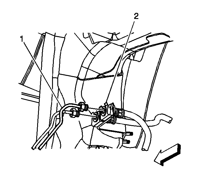
- Disconnect the rear brake pipe lines (1) forward of the rear wheelhouse.
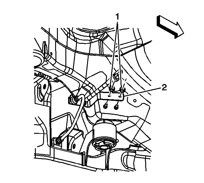
- Remove the fastener for the brake pipe bracket (1).
- Remove the brake pipe bracket (2) from the studs in the body.
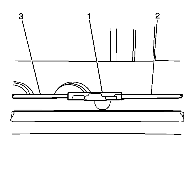
- Disconnect the intermediate park brake cable (2) from the front park brake cable connector.
- Remove the intermediate park brake cable from body bracket.
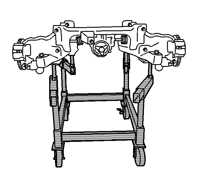
- Position the frame support table J 39580 .
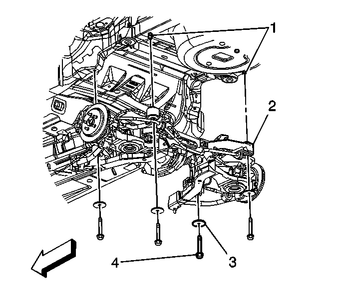
- Remove the frame to body mounting bolts (4) and washers (3).
- Carefully raise the vehicle from the rear frame assembly.
- Remove the following components from the rear frame:
- With the aid from an assistant, remove the frame from the hydraulic jack.
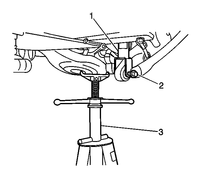
Note: The lower control arms will drop approximately 3 inches when the shock to lower control arm bolts are removed.
| • | The rear brake pipes |
| • | Parking Brake Rear Cable Replacement - Left Side or Parking Brake Rear Cable Replacement - Right Side |
Installation Procedure
- With the aid from an assistant, position and secure the new rear frame on the engine support fixture.
- Install the following components to the rear frame assembly:
- Index the rear coil springs to the spring insulators.
- Ensure the intermediate park brake cable is positioned over left side frame assembly on the left side.
- Lower the vehicle to the frame.
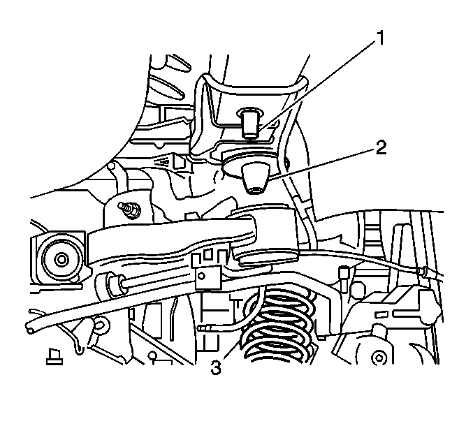
- Position the coil springs (3) to the upper spring insulator (2).
- Index the rear side frame mounts to the rear locator sleeves (1) located on the body.
- Lower the vehicle until the frame mounts contact the body rail.
- Install the rear frame washers (3) and anchor bolts (4).
- Raise the vehicle.
- Remove the J 39580 .
- Install the support fixture (3) in order to raise the lower control arms for ease of lower shock bolt installation (2).
- Install the lower shock bolt (2) to 150 N·m (111 lb ft).
- Repeat the above step for the other side.
- Remove the support fixture (3).
- Install the intermediate park brake cable to the body bracket.
- Connect the intermediate park brake cable (2) to the front park brake cable connector.
- Position the brake pipe bracket (2) to the body studs.
- Install the brake pipe bracket retaining nuts (1) and tighten to 10 N·m (89 lb in).
- Connect the rear brake lines (1) at the forward rear wheelhouse and tighten the lines to 15 N·m (11 lb ft).
- Connect the rear WSS electrical connectors.
- Secure the WSS electrical harness retainer clips to the upper control arms.
- Install the propeller shaft. Refer to Rear Propeller Shaft Replacement.
- Install the exhaust system. Refer to Exhaust System Replacement.
- Install the rear wheels. Refer to Tire and Wheel Removal and Installation.
- Lower the vehicle.
- Bleed the hydraulic brake system. Refer to Hydraulic Brake System Bleeding.
- Align the vehicle. Refer to Wheel Alignment Measurement.

| • | Parking Brake Rear Cable Replacement - Left Side or Parking Brake Rear Cable Replacement - Right Side |
| • | The rear brake pipes |
Note: The rear coil springs need to be indexed into the lower spring insulators prior to assembly.
Note: Ensure the intermediate brake cable is clear of the front frame to body mount prior to securing the frame bolts.

Caution: Refer to Fastener Caution in the Preface section.
| • | Tighten the front bolts to 250 N·m (180 lb ft). |
| • | Tighten the rear bolts to 191 N·m (141 lb ft). |


