For 1990-2009 cars only
Removal Procedure
- Remove the intake manifold. Refer to Intake Manifold Replacement .
- Remove the left ignition coil. Refer to Ignition Coil Replacement - Bank 2 in Engine Controls-2.6L and 3.2L.
- Disconnect the following from the front of the throttle body heater inlet hose/pipe bracket.
- Disconnect the heated oxygen sensor connector (2) from the rear of the throttle body heater inlet hose/pipe (3).
- Remove the bolt securing the throttle body heater inlet hose/pipe to the engine rear lift bracket and position aside.
- Remove the left camshaft cover bolts (1).
- Remove the left camshaft cover (2) from the cylinder head.
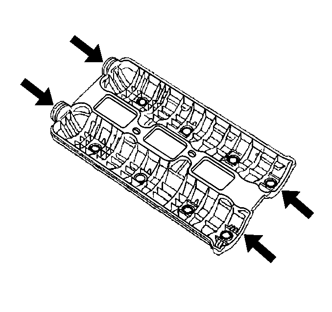
- Remove the left camshaft cover seals (3).
- Clean and inspect the cylinder head sealing surface.
- Clean and inspect the left camshaft cover. Refer to Camshaft Cover Cleaning and Inspection .
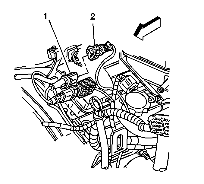
| • | The camshaft position (CMP) sensor connector |
| • | The left knock sensor connector (1) |
| • | The vacuum pipe retainer |
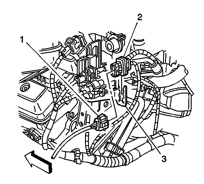
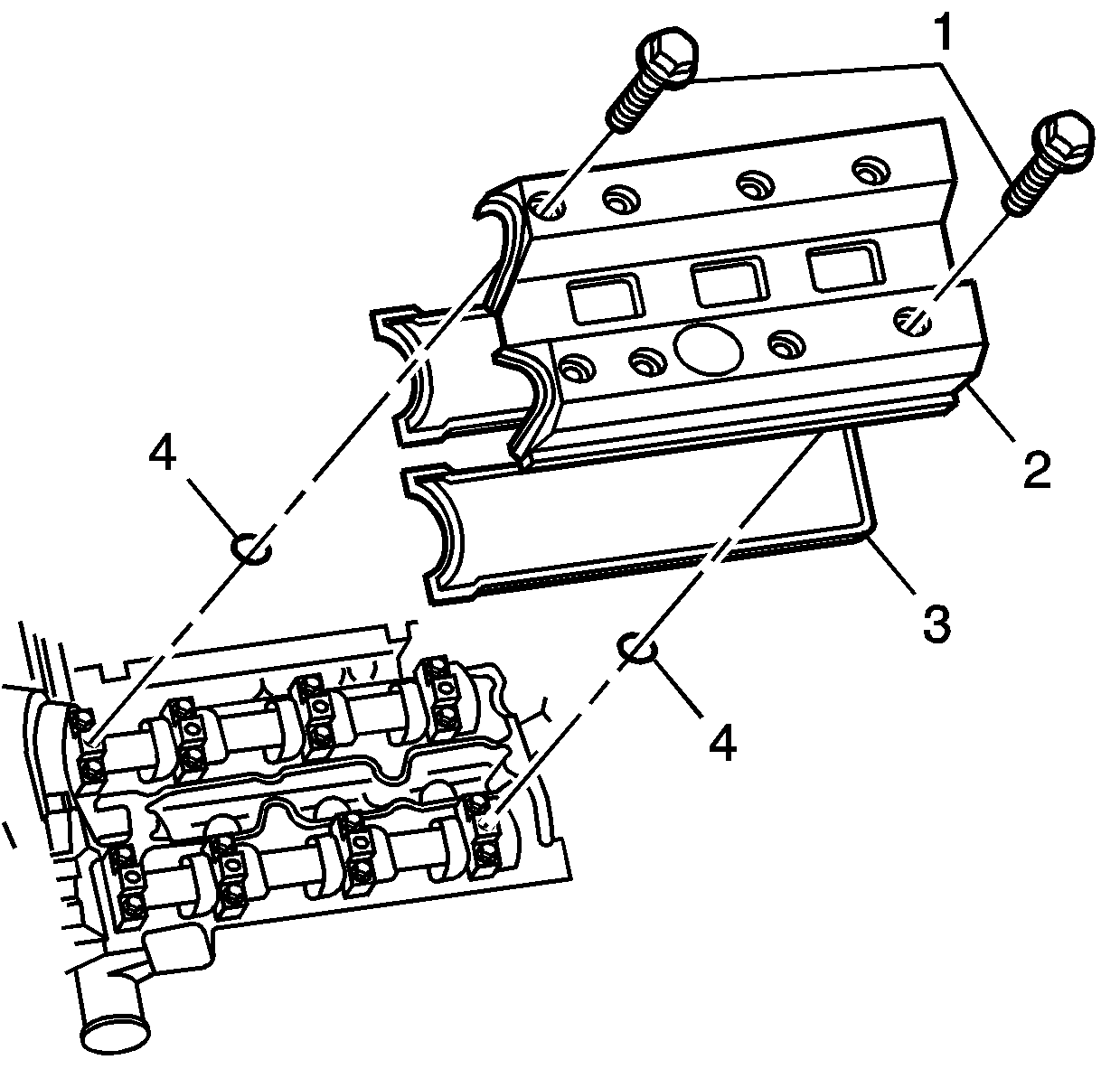
Important: Ensure all 8 sealing O-ring seals (4) are accounted for. The O-ring seals (4) may stick to the camshaft bearing caps or they may fall into the oil return journals in the cylinder head.
Installation Procedure
- Lightly coat the new O-ring seals with clean engine oil prior to installation to assist in holding the O-ring seals to the camshaft cover.
- Install the camshaft cover seals to the camshaft cover.
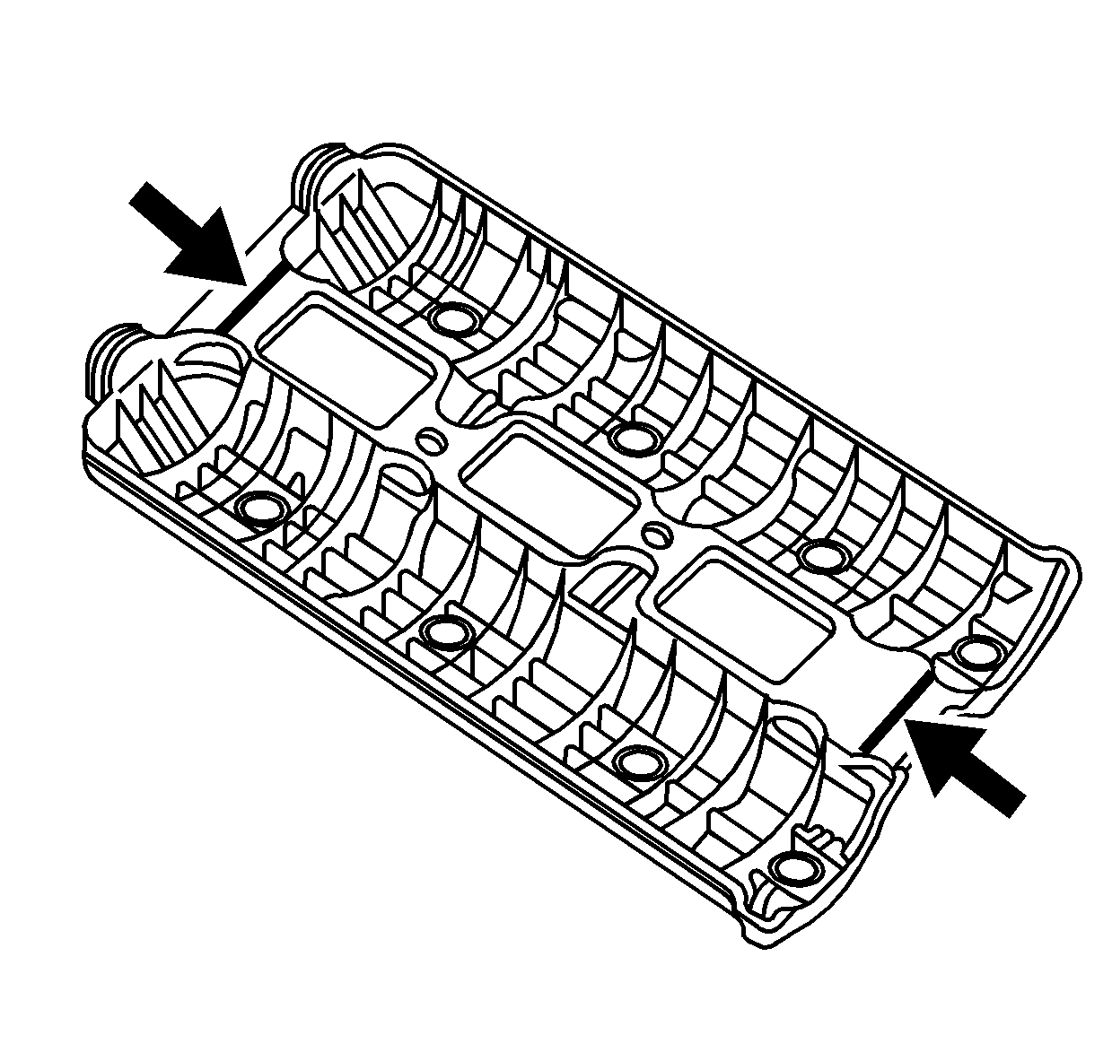
- Apply a thin coat of silicone sealer GM P/N 12346286 (Canadian P/N 10953472), to the corners of the front and back of the seals.
- Apply a 3 mm (0.12 in) bead of silicone sealer GM P/N 12346286 (Canadian P/N 10953472), at the front and rear of the camshaft cover between the seals.
- Position the camshaft cover (2) to the cylinder head, aligning the datum with the hole in the cylinder head.
- Install the camshaft cover bolts (1).
- Install the bolt securing the throttle body heater inlet hose/pipe to the engine rear lift bracket.
- Connect the heated oxygen sensor connector (2) to the rear of the throttle body heater inlet hose/pipe (3).
- Connect the following to the front of the throttle body heater inlet hose/pipe bracket.
- Install the left ignition coil. Refer to Ignition Coil Replacement - Bank 2 in Engine Controls-2.6L and 3.2L.
- Install the intake manifold. Refer to Intake Manifold Replacement .
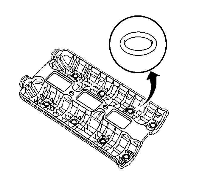

Notice: Refer to Fastener Notice in the Preface section.
Tighten
Tighten the camshaft cover bolts to 8 N·m (71 lb in).
Tighten
Tighten the throttle body heater inlet hose/pipe bolts to 9 N·m
(80 lb in).


| • | The CMP sensor connector |
| • | The left knock sensor connector (1) |
| • | The vacuum pipe retainer |
