For 1990-2009 cars only
Clutch Pedal Replacement CTS
Removal Procedure
- Remove the driver side instrument panel insulator. Refer to Instrument Panel Insulator Panel Replacement - Left Side in Instrument Panel, Gages and Console.
- Disconnect the clutch pedal position switch electrical connector.
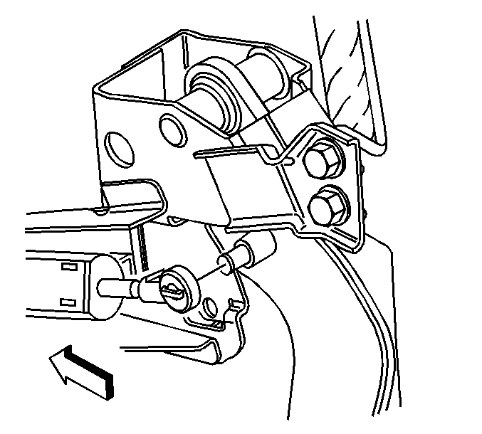
- Disconnect the clutch master cylinder push rod from the clutch pedal pin.
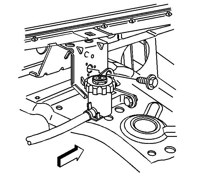
- Remove the clutch fluid reservoir attaching bolt.
- Position the clutch fluid reservoir aside.
- Remove the coolant surge tank and the vacuum brake booster. Refer to Power Vacuum Brake Booster Replacement in Hydraulic Brakes.
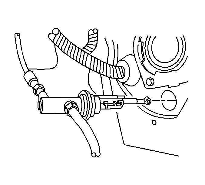
- Rotate the clutch master cylinder clockwise 1/8 turn.
- Remove the clutch master cylinder from the cowl.
- Remove the park brake pedal assembly from the instrument panel and position aside. Refer to Parking Brake Lever Pedal Assembly Replacement in Park Brake.
- Remove the wiring harness retainers from the clutch pedal assembly.
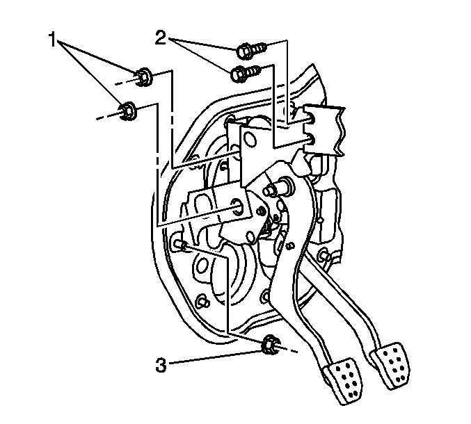
- Remove the 2 bolts (2) securing the clutch pedal assembly to the instrument panel carrier.
- Remove the 2 nuts (1) securing the clutch pedal assembly to the brake pedal assembly.
- Remove the nut (3) securing the clutch pedal assembly to the cowl.
- Remove the clutch pedal assembly from the vehicle.


Important: Do NOT disconnect the hydraulic hoses from the clutch master cylinder.


Installation Procedure
- Install the clutch pedal assembly to the vehicle.
- loosely install the nuts (1), bolts (2), and nut (3) in order to align the clutch pedal assembly.
- Tighten the clutch pedal fasteners in the following order.
- Install the wiring harness retainers to the clutch pedal assembly.
- Install the park brake pedal assembly. Refer to Parking Brake Lever Pedal Assembly Replacement in Park Brake.
- With the clutch fluid reservoir connection at 2:00 position. Insert the clutch master cylinder into the cowl.
- Align the keys of the clutch master cylinder housing with the tabs on the clutch pedal bracket.
- Rotate the clutch master cylinder counter clockwise approximately 1/8 turn until fully seated. The clutch fluid reservoir hose connection will be at vertical 12:00 position when the clutch master cylinder is properly installed.
- Install the vacuum brake booster and the coolant surge tank. Refer to Power Vacuum Brake Booster Replacement in Hydraulic Brakes.
- Install the clutch fluid reservoir.
- Install the clutch fluid reservoir attaching bolt.
- Position the clutch master cylinder push rod to the clutch pedal pin.
- Push the clutch master cylinder push rod onto the clutch pedal pin to secure.
- Connect the clutch pedal position switch electrical connector.
- Check for proper clutch pedal movement and operation.
- Install the driver side instrument panel insulator. Refer to Instrument Panel Insulator Panel Replacement - Left Side in Instrument Panel, Gages and Console.

Notice: Refer to Fastener Notice in the Preface section.
| 3.1. | Tighten the nuts (1). |
Tighten
Tighten the nuts to 20 N·m (15 lb ft).
| 3.2. | Tighten the bolts (2). |
Tighten
Tighten the bolts to 20 N·m (15 lb ft).
| 3.3. | Tighten the nut (3) |
Tighten
Tighten the nut to 9 N·m (80 lb in).


Tighten
Tighten the bolt to 50 N·m (37 lb ft).

