For 1990-2009 cars only
Tools Required
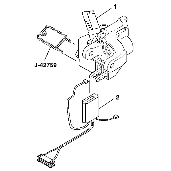
J-42759 Ignition Switch Connector Release Tool
Removal Procedure
- Disable the SIR system.
- Remove the theft deterrent control module. Refer to Theft Deterrent Module Replacement in Theft Deterrent.
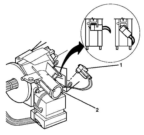
- Rotate the key alarm connector (1) 90 degrees.
- Gently pull the key alarm connector (1) out of the ignition lock cylinder case assembly (2).
- Disconnect the connector from the ignition switch assembly.
- Remove the wires encased in the ignition switch clip (located on the side of the ignition switch).
- Remove the ignition switch assembly (2) using J-42759 .
Caution: Refer to SIR Caution in the Preface section.


Installation Procedure
- Insert J-42759 into the ignition lock cylinder case assembly (1) and slide the ignition switch assembly (2) in.
- Connect the connector to the ignition switch assembly (2).
- Push the key alarm connector (1) into the ignition lock cylinder case assembly (2).
- Rotate the key alarm connector (1) 90 degrees so that the key alarm connector (1) locks into place.
- Install the wires back into the ignition switch clip.
- Install the theft deterrent control module. Refer to Theft Deterrent Module Replacement in Theft Deterrent.
- Enable the SIR system. Refer to SIR Disabling and Enabling in SIR.


Caution: Improper routing of the wire harness assembly may damage the inflatable restraint steering wheel module coil. This may result in a malfunction of the coil, which may cause personal injury.
