Removal Procedure
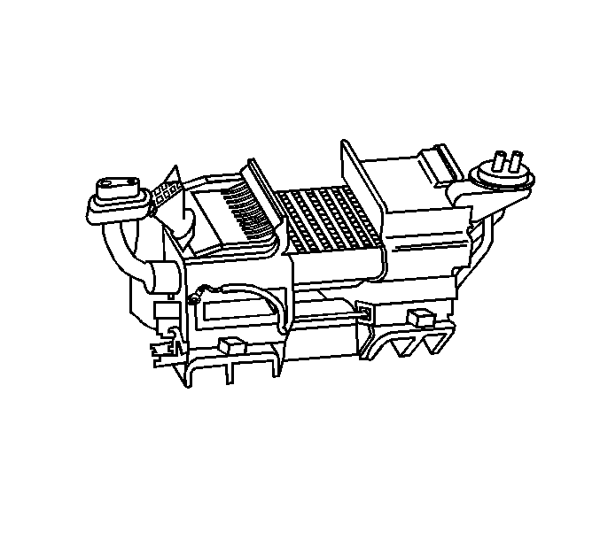
- Remove the HVAC module assembly. Refer to HVAC Module Assembly Replacement .
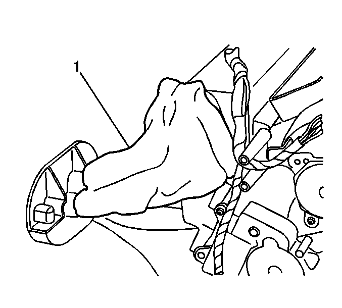
- Remove the insulation (1) from the thermal expansion valve (TXV).
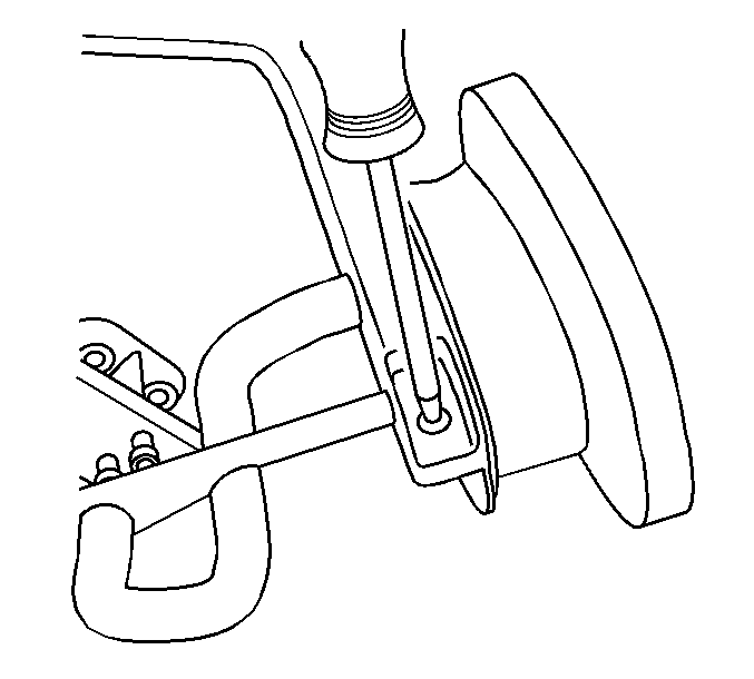
- Remove the HVAC line clamp screw.
- Remove the HVAC line clamp.
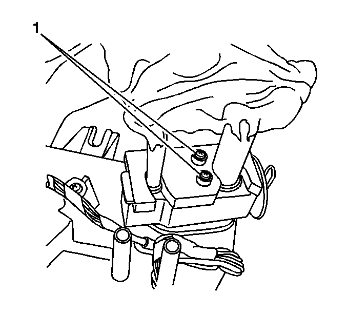
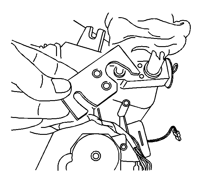
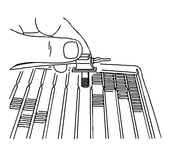
- Remove the TXV to evaporator bolts (1).
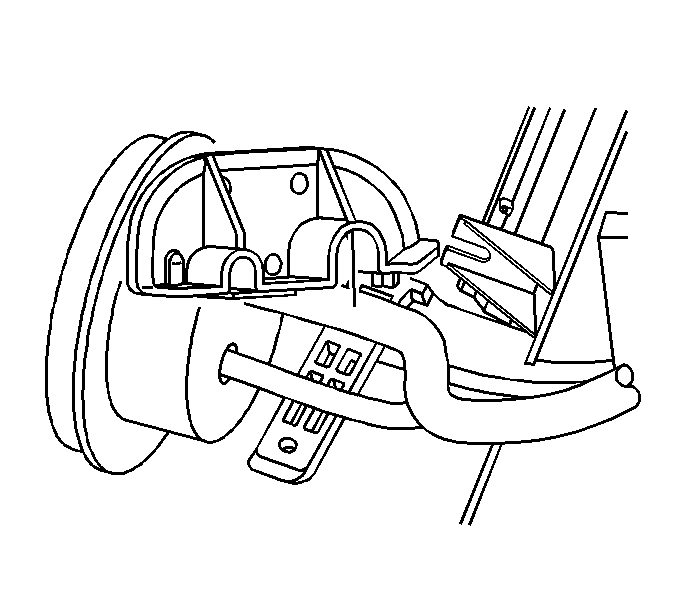
- Remove the TXV line bracket.
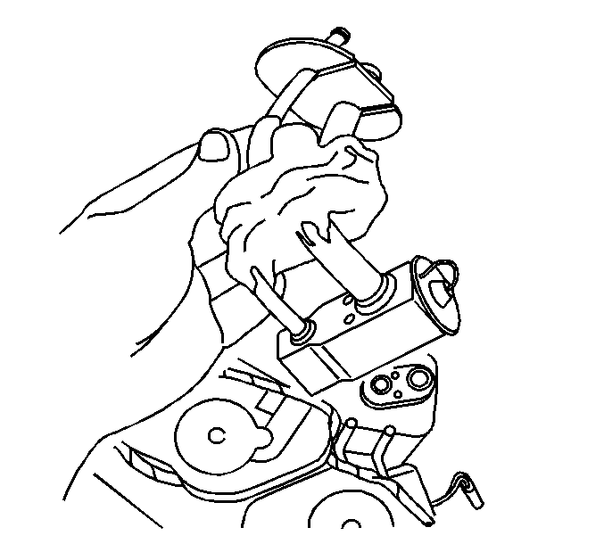
- Remove the TXV from the evaporator core.
- Separate the TXV from the A/C lines by pulling straight out.
- Remove the TXV.
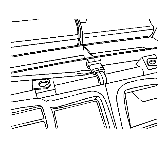
- Remove the screws that hold the case together.
- Remove the clips that hold the case together.
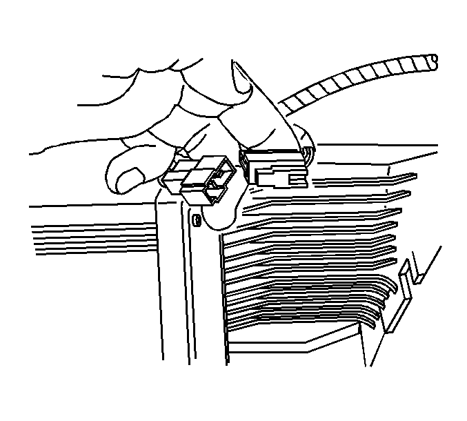
- Disconnect the thermistor electrical connector.
- Separate the HVAC module.
- Remove the thermistor from the evaporator core.
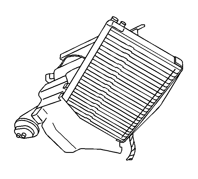
- Remove the evaporator core.
Installation Procedure
- Add refrigerant oil. Refer to Refrigerant System Capacities .
- Install new evaporator core seals to evaporator.
- Install the evaporator core.
- Install the thermistor to the evaporator into the same position as removed.
- Slide the HVAC module together.
- Install the screws that hold the case together.
- Install the clips that hold the case together.
- Connect the thermistor electrical connector.
- Lube A/C lines with refrigerant oil before installing. Refer to O-Ring Replacement .
- Install the A/C lines into the TXV.
- Carefully slide the TXV onto the evaporator core until seated.
- Install the TXV line bracket.
- Install the TXV to evaporator bolts (1).
- Install the HVAC line clamp.
- Install the HVAC line clamp screw.
- Install the insulation (1) onto the lines and TXV.
- Install the HVAC module. Refer to HVAC Module Assembly Replacement .


Notice: Use the correct fastener in the correct location. Replacement fasteners must be the correct part number for that application. Fasteners requiring replacement or fasteners requiring the use of thread locking compound or sealant are identified in the service procedure. Do not use paints, lubricants, or corrosion inhibitors on fasteners or fastener joint surfaces unless specified. These coatings affect fastener torque and joint clamping force and may damage the fastener. Use the correct tightening sequence and specifications when installing fasteners in order to avoid damage to parts and systems.
Tighten
Tighten the screws to 1 N·m (8 lb in).


Notice: Refer to Fastener Notice in the Preface section.

Tighten
Tighten the bolts to 3.5 N·m (31 lb in).


Tighten
Tighten the screw to 1 N·m (8 lb in).

