For 1990-2009 cars only
Liquid Line Replacement LHD, LA3, LY9
Tools Required
| • | J 39400-A Halogen Leak Detector |
| • | J 45689 A/C Quick Joint Tool |
Removal Procedure
- Recover the refrigerant. Refer to Refrigerant Recovery and Recharging .
- Remove the air cleaner from the vehicle. Refer to Air Cleaner Assembly Replacement in Engine Controls 2.6L and 3.2L.
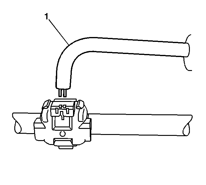
- Disconnect the A/C high pressure switch electrical connector (1) from the switch (2).
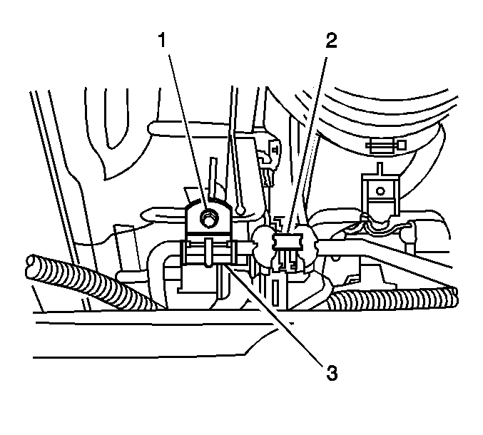
- Remove the retaining clip screw (1) from the A/C line.
- Using the J 45689 disconnect the quick joint (2) by pressing the probe end into the two small openings on the quick joint.
- Remove the liquid line from the strut tower retaining clip (1).
- Using the J 45689 disconnect the liquid line at the evaporator fitting .
- Remove the liquid line from the vehicle.
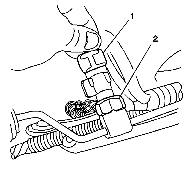
Important: The body of the tool (1) should be parallel to the A/C line.
Installation Procedure
- Coat new O-rings with refrigerant oil. Refer to O-Ring Replacement .
- Install the liquid line in to the vehicle.
- Secure the liquid line into the bracket (1) on the strut tower.
- Connect the liquid line to the evaporator.
- Install the A/C quick connect clamp (1) on the line.
- Engage the clamp.
- Gently tug on the liquid line to ensure that the clamp is engaged.
- Connect the liquid line at the condenser.
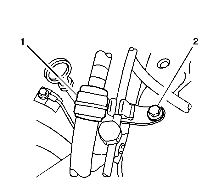
- Install the retaining clip screw (1) to the A/C line.
- Install the A/C quick connect clamp on the line.
- Gently tug on the liquid line to ensure that the clamp (2) is engaged.
- Connect the high pressure switch electrical connector (1) to the switch (2).
- Install the air cleaner assembly. Refer to Air Cleaner Assembly Replacement in Engine Controls 2.6L and 3.2L.
- Evacuate and recharge the refrigerant system. Refer to Refrigerant Recovery and Recharging .
- Leak test the fittings of the repaired or reinstalled component using the J 39400-A .
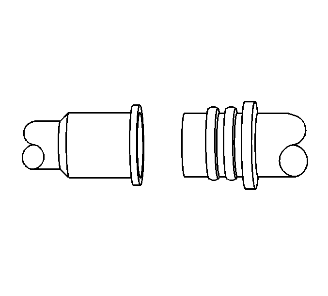

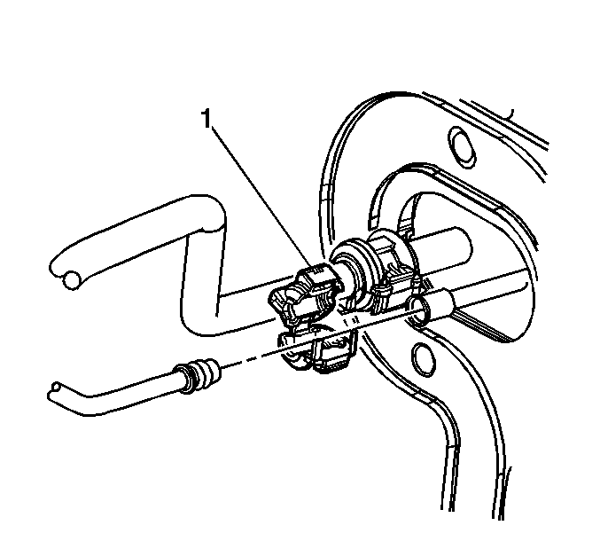
Important: Squeeze the clamp together until you here it engage.

Notice: Refer to Fastener Notice in the Preface section.
Tighten
Tighten the screw to 9.8 N·m (87 lb in).

Liquid Line Replacement RHD, LA3, LY9
Tools Required
| • | J 39400-A Halogen Leak Detector |
| • | J 45689 A/C Quick Joint Tool |
Removal Procedure
- Recover the refrigerant. Refer to Refrigerant Recovery and Recharging .
- Remove the battery. Refer to Battery Replacement in Engine Electrical.
- Remove the air cleaner from the vehicle. Refer to Air Cleaner Assembly Replacement in Engine Controls 2.6L and 3.2L.
- Disconnect the A/C high pressure switch electrical connector (1) from the switch (2).
- Using the J 45689 disengage the clamp (2) at the fan assembly.
- Remove the retaining clip screw (1) from the A/C line.
- Using J 45689 , disconnect the quick joint (2) by pressing the probe end into the two small openings on the quick joint.
- Remove the liquid line from the strut tower retaining clip (1).
- Using J 45689 disconnect the liquid line at the evaporator fitting.
- Remove the liquid line from the vehicle.


Important: The body of the tool (1) should be parallel to the A/C line.

Installation Procedure
- Coat new O-rings with refrigerant oil. Refer to O-Ring Replacement .
- Install the liquid line in to the vehicle.
- Secure the liquid line into the bracket (1) on the strut tower.
- Connect the liquid line to the evaporator.
- Install the A/C quick connect clamp (1) on the line.
- Engage the clamp.
- Gently tug on the liquid line to ensure that the clamp is engaged.
- Connect the liquid line at the condenser.
- Install the retaining clip screw (1) to the A/C line.
- Install the A/C quick connect clamp on the line.
- Gently tug on the liquid line to ensure that the clamp (2) is engaged.
- Connect the high pressure switch electrical connector (1) to the switch (2).
- Install the air cleaner assembly. Refer to Air Cleaner Assembly Replacement in Engine Controls 2.6L and 3.2L.
- Install the battery. Refer to Battery Replacement in Engine Electrical.
- Evacuate and recharge the refrigerant system. Refer to Refrigerant Recovery and Recharging .
- Leak test the fittings of the repaired or reinstalled component using the J 39400-A .


Important: Squeeze the clamp together until you here it engage.

Notice: Refer to Fastener Notice in the Preface section.
Tighten
Tighten the screw to 9.8 N·m (87 lb in).

