Key Identification and Usage
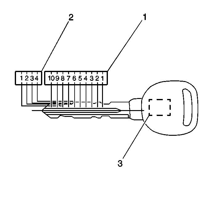
The keys are double sided and reversible. Each key contains a key transponder that interacts with the theft deterrent system on the vehicle when the keys are inserted into the ignition lock cylinder. The keys have 10 key cut positions (1) with 4 different cut depths (2) and can be identified by a PK3+ stamped on the key blade.
The keys that are furnished with the vehicle are two Cadillac master keys that will operate all of the lock cylinders on the vehicle.
Cutting Keys

The key code can be obtained from the 4 digit number located on the key tag that accompanies the original keys. The 4 digit number cross references to a key code and tumbler sequence. The key code can also be determined by examining the key cut positions and cut depths on the actual key (1).
Each key has ten key cut positions (1) and four key cut depths (2). The Key cut positions are numbered 1-10, counting from the head of the key to the tip. The key cut depths are 1-4, cut depth number 4 is the deepest cut. The key transponder (3) in the keys must be programmed to the vehicle. Refer to Programming Theft Deterrent System Components in Theft Deterrent.
- Cut a blank key with the proper key cut position and key cut depth according to the tumbler sequence in the lock cylinders or the key code on the original key.
- Inspect the mechanical operation of the duplicated key in the one front side door lock cylinder and the ignition lock cylinder to insure proper fit and function.
- If replacing a master or duplicating a key, program the key transponder to the vehicle.
| • | If a learned master key is available, refer to Adding Keys in Theft Deterrent. |
| • | If a learned master key is not available, refer to Replacing Keys in Theft Deterrent. |
Lock Cylinder Tumbler Operation
Each of the 4 cut depths on the key has corresponding double-throw tumbler, sometimes referred to as plates or wafers. The tumbler depth number is stamped on the tumblers for identification. The ignition lock cylinder and front side door lock cylinder share common tumblers that are not self-retaining. The IP compartment door lock cylinder uses unique tumblers that are self-restraining. The IP compartment door lock cylinder also requires a retaining tumbler that does not move when the key is inserted. Its function is to retain the lock cylinder in the corresponding latch assembly.
Assembling and Coding the Ignition Lock Cylinder
The ignition lock cylinder uses nine of the ten cut positions, 1-9. The tumbler positions are staggered from side to side, five on one side and four on the other.
- Hold the uncoded cylinder assembly (4) so the side with five tumbler spring wells is facing upward.
- Insert one tumbler spring (3) into the five tumbler spring wells.
- The first tumbler to be loaded will be key cut position, number 1. Determine the cut depth at this position and install the corresponding tumbler (2) into the tumbler slot nearest the front of the cylinder Assembly (5) the end where the key is inserted. It may be necessary to move the sidebar (4) already pre-assembled in to the uncoded cylinder assembly (5) out slightly to full install the tumbler (2) into the correct tumbler slot.
- Install the 4 remaining tumblers on this side of the lock cylinder, key cut positions 3, 5, 7 and 9.
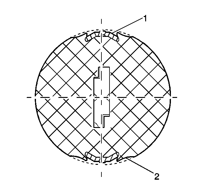
- Inspect for correct loading of the tumblers (2) by inserting the key into cylinder (5). The sidebar (4) should be flush with the outside diameter of the cylinder (5).
- Turn the cylinder (5) so that the side with the 4 tumbler spring wells is facing up. Remove the key.
- Insert the tumbler springs (3) into the four tumbler spring wells.
- Install the tumbler (2) for the key cut position 2 into the slot nearest to the front of the lock cylinder.
- Install the three remaining tumblers, key cut positions 4, 6 and 8, on this side of the lock cylinder.
- Inspect for correct loading of the tumblers (2) by inserting the key into cylinder (5). The sidebar (4) should be flush with the outside diameter of the cylinder (5).
- Lightly lubricate the tumbler (2) surfaces using the provided lubrication.
- With the key inserted into the housing, install and carefully stake one tumbler retainer (1) into the recessed area (5) on the cylinder.
- Turn over the cylinder and carefully stake the other tumbler retainer (1) into the recessed area (5) on the cylinder.
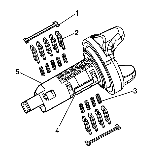
Important: The ignition lock cylinder tumblers (2) are not self retaining and must be held in place if the key is not fully inserted into the lock cylinder, or until the tumbler retainer (1) is properly staked into the cylinder.

Assembling and Coding the IP Compartment Door Lock Cylinder
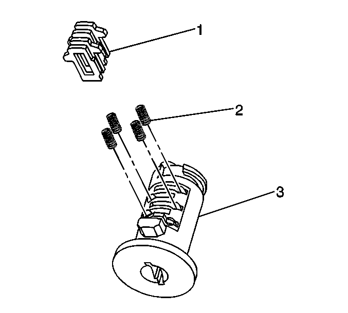
The IP compartment door lock cylinder uses 4 of the ten cut positions 7-10. The retainer tumbler position is adjacent locations with all four tumblers (3) located on the same side. A stainless steel retaining tumbler is used in the IP compartment door lock cylinder to retain the lock cylinder in the latch assembly and does not move when the key is inserted. . The retainer tumbler occupies the slot closest to the head of the cylinder assembly (1) and comes pre-installed in the cylinder.
- Hold the cylinder (3) so that the side with 4 tumbler spring wells is facing up.
- Insert tumbler springs (2) into the 4 spring wells.
- The first tumbler to be loaded will be key cut position Number 7. Determine the cut depth at this position and install the corresponding tumbler (1) into the slot nearest to the front of the lock cylinder (3).
- Install the three remaining tumblers, key cut positions 8, 9 and 10, into the cylinder.
- Snap the tumblers into place with light hand pressure.
- Inspect for the correct loading of the tumblers (1) by inserting the key into cylinder (3). All of the tumblers should be flush with the lock cylinder.
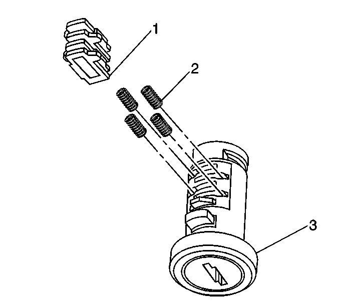


Assembling and Coding IP Storage Compartment Lock Cylinder
The IP storage compartment lock only uses 4 of the ten cut positions 7-10 . A retainer tumbler is used in the IP storage compartment lock to retain the lock cylinder in the latch assembly. This retainer tumbler is not moved by the key. The retainer tumbler occupies the slot closest to the head of the IP storage compartment lock cylinder and should come already installed in the cylinder.
- Hold the cylinder (3) so that the side with 4 tumbler spring wells is facing up.
- Insert tumbler springs (2) into the 4 spring wells.
- Install the tumbler (1) for key cut position 7 into the slot nearest to the front of the lock cylinder.
- Install the three remaining tumblers, key cut positions 8, 9 and 10, into the cylinder.
- Snap the tumblers into place with light hand pressure.
- Inspect for the correct loading of the tumblers (1) by inserting the key into cylinder (3). All of the tumblers should be flush with the lock cylinder.


Assembling and Coding the Front Side Door Lock Cylinder
The front side door lock cylinder only uses seven of the ten cut positions, 4 through 10. The tumbler positions are staggered from side to side with four on one side and three on the other. The left and right door lock cylinders are identical except for the lever (2) and rod retainer (1). The right lever is color-coded, yellow and stamped with the letter R and the left lever is color-coded olive drab and stamped with the letter L. The right rod retainer is color coded yellow and the left rod retainer is color-coded green. The lock pawl determines which side of the vehicle the lock cylinder will be installed.
- Hold the cylinder (9) so that the side with 4 tumbler spring wells faces upward.
- Insert tumbler springs (5) into the 4 spring wells.
- Install the tumbler for key cut position 4 in the slot nearest to the front of the lock cylinder (2).
- Install the three remaining tumblers, key cut positions 6, 8 and 10, on this side of the lock cylinder.
- Inspect for correct loading of the tumblers (10) by inserting the key into cylinder (9). All of the tumblers should be flush with the outside diameter of the lock cylinder.
- Turn the cylinder (9) so that the side with three tumbler spring wells faces up.
- Insert the tumbler springs (5) into the three spring wells.
- Install the tumbler for key cut position 5 into the slot nearest the front of the lock cylinder (1).
- Install the two remaining tumblers for key cut positions 7 and 9 on this side of the lock cylinder.
- Inspect for correct loading of the tumblers (10) by inserting the key into cylinder (9). All of the tumblers should be flush with the outside diameter of the lock cylinder.
- Lightly lubricate the tumbler (10) surfaces using the provided lubrication.
- Hold the case assembly (11) with the pre-staked detent spring retainer facing downward.
- Insert one detent spring (3) and one detent ball (4) into the hole located to the rear and inside of the case assembly (11).
- Insert the key into the lock cylinder.
- Ensure the detent spring (3) and ball (4) are held in place until the cylinder is fully installed. Install the cylinder into the case assembly (11). The detent ball (4) will line up with the V-shaped groove on the rear of the cylinder.
- Carefully remove the key, keeping the lock cylinder (9) inserted into the case assembly (11).
- Insert one shutter spring (8) into each hole located on the front of the cylinder (9).
- Install the shutter assembly (7) into the recessed area in the front of the cylinder (9). Ensure the ends of the pin on the shutter assembly (7) are positioned in the pin cavities located on the front face of the cylinder (9).
- Install the lock cylinder cap (6) by aligning the two notches in the cap with the drain hole located on the bottom of the case assembly (11) and the corresponding feature on the top of the case assembly (11).
- Install the appropriate lever (2).
- Install the retaining ring (12).
- Snap the appropriate rod retainer (1) into the hole in the lever (2).
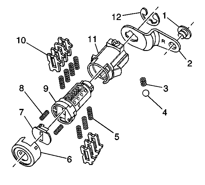
Important: The front side door lock cylinder tumblers (10) are not self retaining and must be held in place if the key is not fully inserted into the lock cylinder, or until the cylinder (9) is assembled into the case assembly (11).


Caution: Wear safety glasses in order to avoid eye damage.
Press the cap into place with light hand pressure.
Assembling and Coding the IP Compartment Door Lock Cylinder
The IP compartment door lock cylinder uses four of the ten cut positions 7-10. The retainer tumbler position is adjacent locations with all four tumblers (1) located on the same side. A stainless steel retaining tumbler is used in the IP compartment door lock cylinder to retain the lock cylinder in the latch assembly and does not move when the key is inserted. . The retainer tumbler occupies the slot closest to the head of the cylinder assembly (3) and comes pre-installed in the cylinder.
- Hold the cylinder (3) so that the side with four tumbler spring wells is facing up.
- Insert tumbler springs (2) into the four spring wells.
- Install the tumbler (1) for key cut position 7 into the tumbler slot nearest to the front of the lock cylinder (3).
- Install the three remaining tumblers, key cut positions 8, 9 and 10, into the cylinder.
- Snap the tumblers (1) into place with light hand pressure.
- Inspect for the correct loading of the tumblers (3) by inserting the key into cylinder (1). All of the tumblers (1) should be flush with the lock cylinder (3).


Assembling and Coding the Front Side Door Lock Cylinder
The front side door lock cylinder uses seven of the ten key cut positions, 4-10. The tumbler positions are staggered from side to side with four on one side and three on the other. The right and left side door lock are identical except for the lever (2) and rod retainer (1). The right lever is color-coded, yellow and stamped with the letter R and the left lever is color coded olive drab and stamped with the letter L. The right rod retainer is color coded yellow and the left rod retainer is color coded green. This determine on which side of the vehicle the lock cylinder will be installed.
- Hold the uncoded cylinder assembly (1) so the side with four tumbler spring wells is facing upward.
- Insert one tumbler spring (5) into the four tumbler spring wells.
- The first tumbler to be loaded will be key cut position, number 4. Determine the cut depth at this position and install the corresponding tumbler (1) into the tumbler slot nearest the front of the lock cylinder Assembly the end where the key is inserted.
- Install the three remaining tumblers on this side of the lock cylinder, key cut positions 6, 8 and 10.
- Inspect for correct loading of the tumblers (10) by inserting the key into cylinder (9). The tumblers (10) should be flush with the outside diameter of the cylinder (9).
- Turn the cylinder (9) so that the side with the three tumbler spring wells is facing upward and then remove the key. The tumbler (10) are not self-retaining and must be held in place.
- Insert the tumbler springs (5) into the three tumbler spring wells.
- The first tumbler to be loaded will be key cut position number 5. Determine the cut depth and install the tumbler (1) into the tumbler slot nearest to the front of the cylinder.
- Install the two remaining tumblers (10), into the tumbler slots located at key cut positions 5, 7 and 9.
- Inspect for correct loading of the tumblers (10) by inserting the key into cylinder (9). The sidebar (10) should be flush with the outside diameter of the cylinder (9).
- Lightly lubricate the tumbler (10) surfaces using the provided lubrication.
- Hold the case assembly (11) with the pre-staked detent spring retainer facing downward.
- First insert one detent spring (3) then one detent ball (4) into the detent spring hole located to the rear and inside of the cylinder case assembly (11). The detent spring (3) and the detent ball (4) are not self-retaining and must be held in place until the coded cylinder is installed into the case assembly.
- With the matching key fully inserted into the coded cylinder install the coded cylinder into the case assembly (11). Insure the detent spring (3) and detent ball (4) are held in place until the coded cylinder is fully installed. The detent (4) should line with the v-shaped groove on the rear of the cylinder which will prevent the detent spring and detent fall from falling out of the case assembly.
- Remove the matching key being careful to keep the coded cylinder (9) fully inserted into the case assembly (11).
- Insert one shutter spring (8) each into the two shutter spring holes located on the front face of the cylinder (9).
- Install the shutter assembly (7) into the recessed area in the front face of the cylinder (9). Ensure that the ends of the pin on the shutter assembly (7) are positioned in the pin cavities located on the front face of the cylinder (9).
- Install the lock cylinder cap (6) by aligning the two notches in the cap with the drain hole located on the bottom of the case assembly (11) and the corresponding feature located on the top of the case assembly. Snap the cap (6) into place with light hand pressure. Insure the cap is securely retained on the case assembly and that the shutter springs (8) push the shutter assembly (7) up against the inside surface of the cap.
- Install the appropriate lever (12) in the groove at the end of the cylinder (9) to secure the lever (2) to the cylinder.
- Install the retaining ring (12) in the groove at the end of the cylinder (9) to secure the lever (2) to the cylinder.
- Snap the appropriate rod retainer (1) right or left into the hole in the lever (2).

Important: The front side door lock cylinder tumblers (10) are not self retaining and must be held in place if the key is not fully inserted into the lock cylinder, or the tumbler retainer (3) is properly staked into the cylinder.


Assembling and Coding the Free-Wheeling Front Side Door Lock Cylinder
The free-wheeling front side door lock cylinder uses eight of the ten key cut positions, 3-10. The tumbler positions are staggered from side to side with four on one side. The right and left side door lock are identical except for the lever (3) and rod retainer (13). The right lever is color-coded, yellow and stamped with the letter R001 and the left lever is color-coded olive drab and stamped with the letter L001. The right rod retainer is color coded yellow and the left rod retainer is color coded green. This determine on which side of the vehicle the lock cylinder will be installed.
- Hold the uncoded cylinder (10) positioned so the sidebar is facing to the left and the four spring wells is facing upward.
- Insert one tumbler spring (6) into the four tumbler spring wells.
- The first tumbler to be loaded will be key cut position, number 4. Determine the cut depth at this position and install the corresponding tumbler (1) into the tumbler slot nearest the front of the lock cylinder assembly, the end where the key is inserted.
- Install the three remaining tumblers (11) into the tumbler slots located at key cut positions 6, 8 and 10.
- Inspect for correct loading of the tumblers (11) by inserting the matching key into the cylinder (10). All tumblers (11) should be flush with the outside diameter of the cylinder (10).
- Turn the cylinder (10) so that the side with the three tumbler spring wells is facing upward and then remove the matching key. The tumbler (11) are not self-retaining and must be held in place.
- Insert the tumbler springs (6) into the four tumbler spring wells.
- The first tumbler to be loaded will be key cut position number 3. Determine the cut depth and install the tumbler (1) into the tumbler slot nearest to the front of the cylinder.
- Install the three remaining tumblers (11) into the tumbler slots located at key cut positions 5, 7 and 9.
- Inspect for correct loading of the tumblers (11) by inserting the matching key into cylinder (10). All tumblers (11) should be flush with the outside diameter of the cylinder (10).
- Lightly lubricate the tumbler (11) surfaces using the provided lubrication.
- Install the sleeve (5) into the case (12). Ensure the sleeve (5) is oriented and inserted so that the back of the sleeve is flush with the back of the case (4).
- With the matching key fully inserted into the coded cylinder, install the coded cylinder into the case assembly (12).
- Remove the matching key being careful to keep the coded cylinder (10) fully inserted into the case assembly (12).
- Insert one shutter spring (9) each into the two shutter spring holes located on the front face of the cylinder (10).
- Install the shutter assembly (8) into the recessed area in the front face of the cylinder (10). Ensure that the ends of the pin on the shutter assembly (8) are positioned in the pin cavities located on the front face of the cylinder (10).
- Install the lock cylinder cap (7) by aligning the rectangular hole in the cap with the drain hole located on the bottom of the case (12). Snap the cap (7) into place with light hand pressure. Insure the cap is securely retained on the case and that the shutter springs (9) is push in the shutter assembly (8) up against the inside surface of the cap.
- Install clutch (4) onto rear end of cylinder (10). Ensure the clutch (4) mates with the engagement tab on the cylinder (10).
- Set return spring (3) onto rear of cylinder assembly with the first leg engaged with the clutch (4).
- Hook second leg of return spring (3) onto opposite clutch (4) finger by compressing and rotating spring leg counter-clockwise. The return spring (3) will need to be help in place until the lever (2) and retaining ring (13) are properly installed.
- Install the appropriate lever (2) right or left onto the end of the cylinder (10) so that the lever (2) engages the fingers of the clutch (4). The ID stamp of the lever (2) should face toward the cap (7) at the front of the cylinder assembly.
- Install the retaining ring (13 in the groove at the end of the cylinder to secure the lever (2) to the cylinder.
- Snap the appropriate rod retainer (1) right or left into the hole in the lever (2).
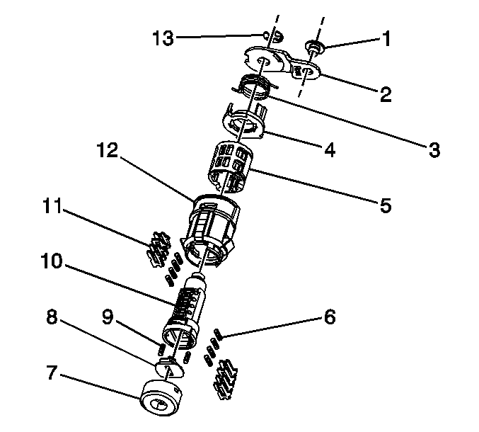
Important: The free-wheeling front side door lock cylinder tumblers (11) are not self retaining and must be held in place if the key is not fully inserted into the lock cylinder or until the cylinder (10) is assembled into the case (12).


