Tools Required
| • | J 38734 Intermediate
Spring Compressor Adapter |
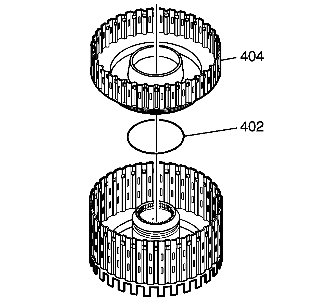
- Inspect the reverse clutch housing (401)
for the following:
| • | Worn or damaged splines |
| • | Seal ring groove nicks or burrs |
| • | Cracked or blocked fluid passages |
| • | Worn or damaged bushing |
- Inspect the reverse clutch piston and the direct clutch piston for the
following:
| • | Cracks or damage to seal grooves |
| • | Damaged ball check valve (405) |
| • | Worn or damaged clutch plates |
- Install the reverse clutch piston inner seal (402).
- Install the reverse clutch piston (404).
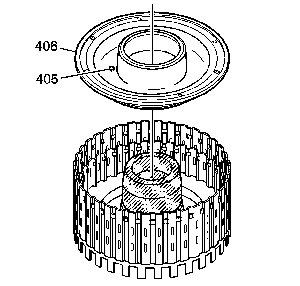
- Install J 45133
onto the direct and reverse clutch assembly (6).
- Install the direct clutch piston (406).
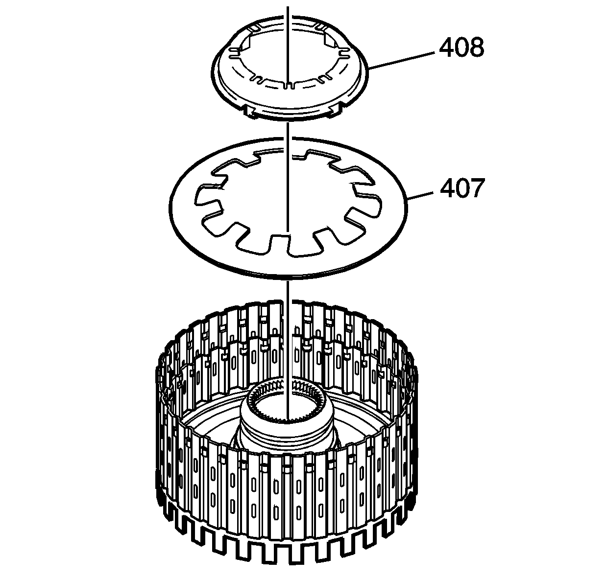
- Install the piston spring (407).
- Install the piston spring retainer (408).
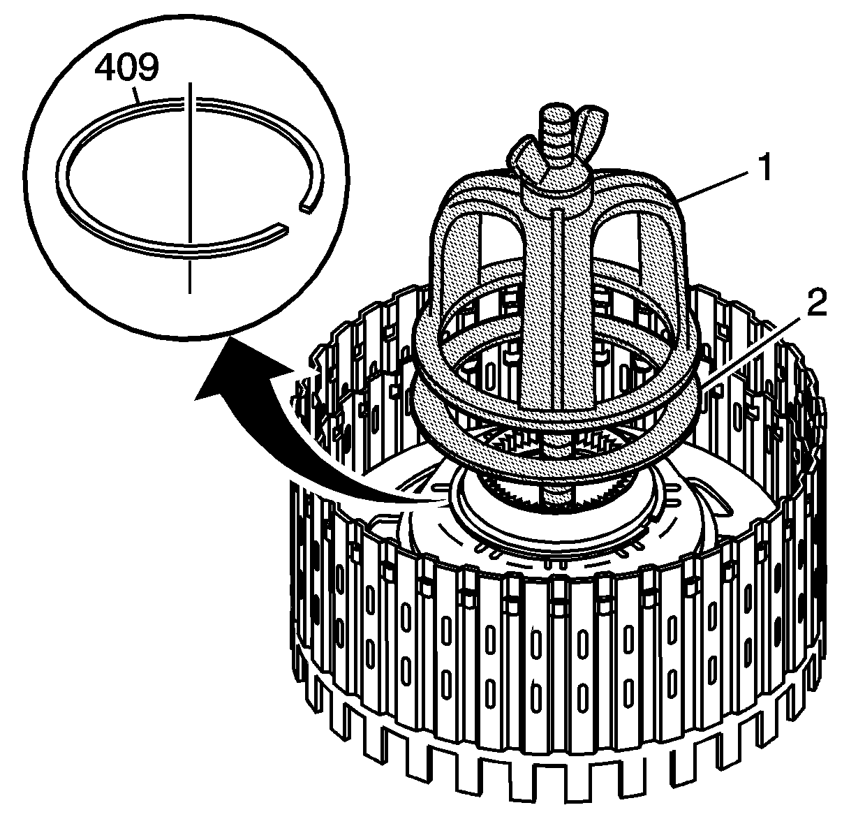
- Use J 38734
(1)
and J 45139
(2) to compress
the direct and reverse piston spring (407).
- Install the new direct and reverse clutch spring retainer ring (409).
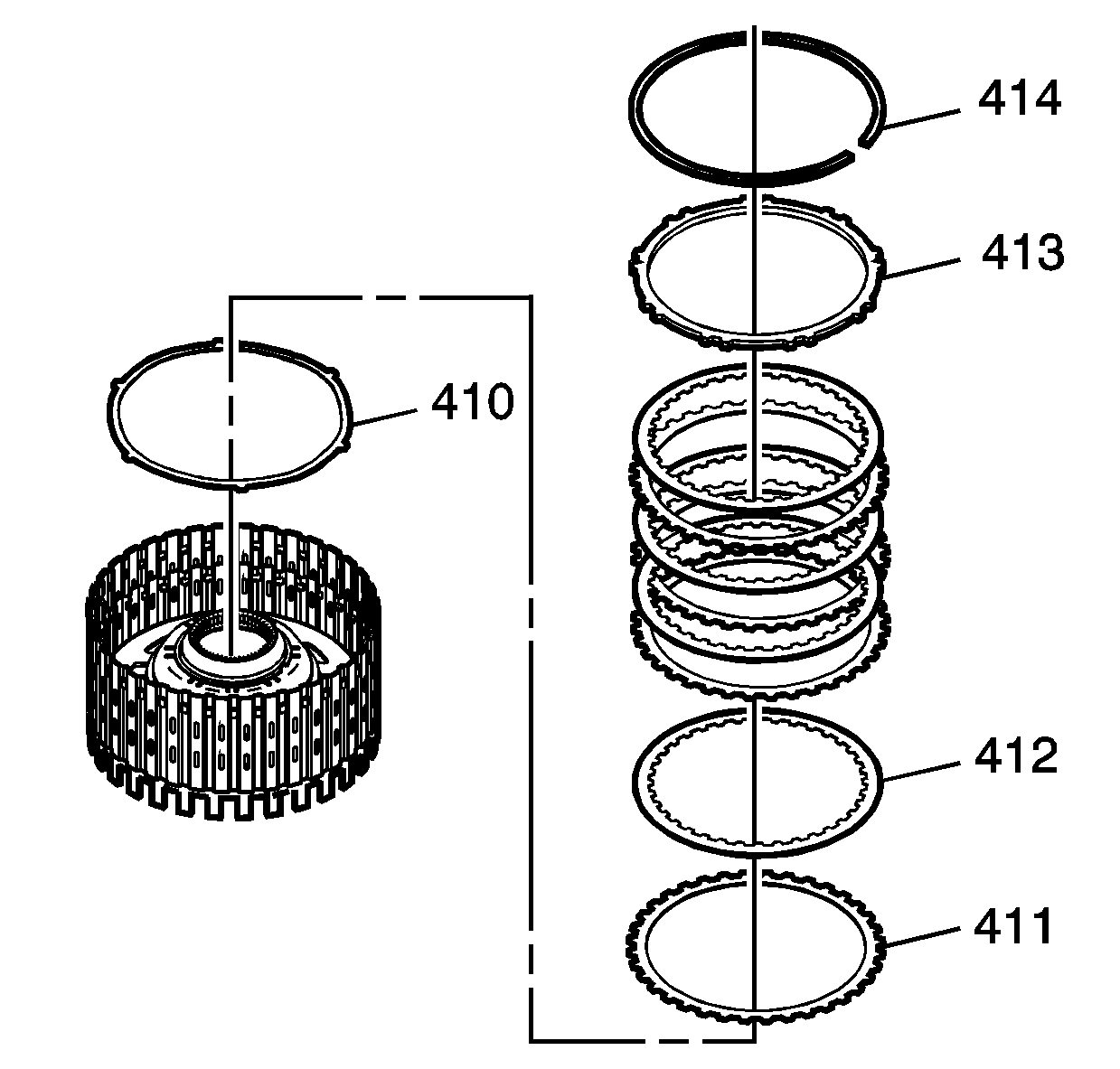
- Install the apply plate (410).
- Install the clutch plates (412, 411), starting with the direct
clutch plate (411) with outer splines, alternating with the direct clutch
plate (412) with inner splines. Refer to
Clutch Plate Selection Specifications
.
- Install the backing plate (413).
- Install the backing plate retainer (414).
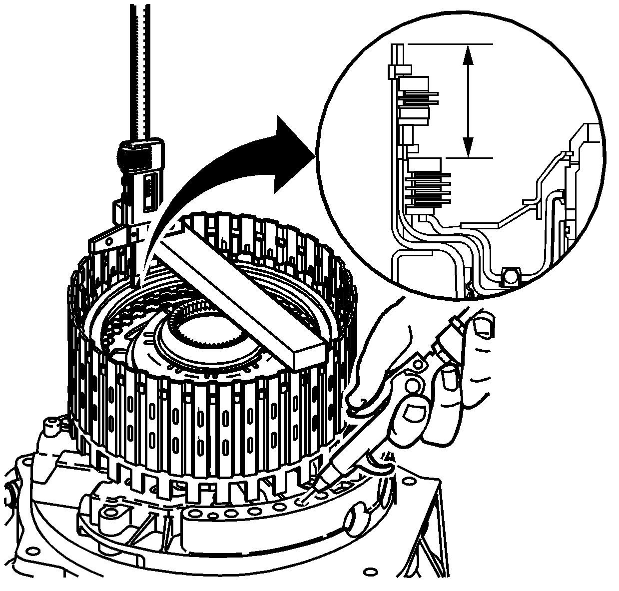
- Measure the distance between the direct
clutch backing plate and the bottom of the gage bar. Measure three times in different
locations on the backing plate. Record this as H1.
- Apply air pressure - 65 PSI, to the specified port. Measure
the distance between the direct clutch backing plate and the bottom of the gage
bar. Measure three times in different locations on the backing plate. Record this
as H2.
- Subtract H2 from H1 this is the clutch pack travel. If the clutch travel
is between 1.86 mm (0.073 in) and 1.06 mm (0.042 in)
use the current direct clutch backing plate retainer ring (414). If the
clutch travel is more than 1.86 mm (0.073 in) use the next size larger
direct clutch backing plate retainer ring (414). If the clutch travel is
less than 1.06 mm (0.042 in) use the next size smaller direct clutch
backing plate retainer ring (414). Refer to Clutch Travel Chart.
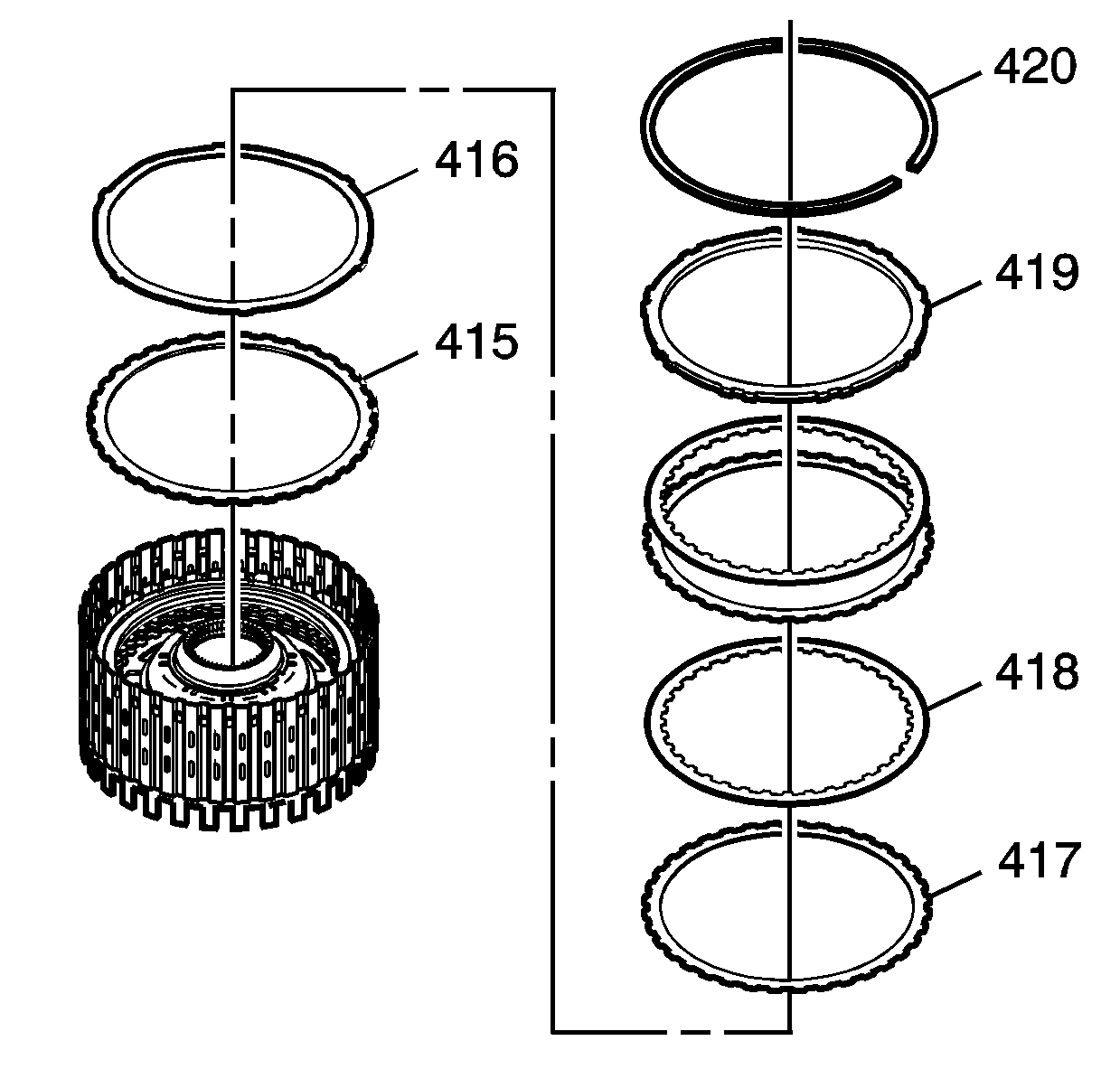
- Install the reverse clutch spacer (415).
- Install the apply plate (416).
- Install the clutch plates (417, 418), starting with clutch plates (417)
with outer splines, alternating with clutch plates (418) with inner splines.
Refer to
Clutch Plate Selection Specifications
.
- Install the reverse clutch backing plate (419).
- Install the reverse clutch backing plate retainer (420).
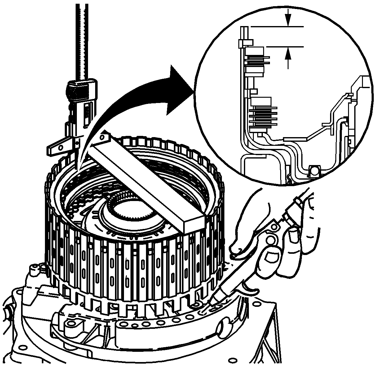
- Measure the distance between the reverse
clutch backing plate and the bottom of the gage bar. Measure three times in different
locations on the backing plate. Record this as H1.
- Apply air pressure - 65 PSI, to the specified port. Measure
the distance between the reverse clutch backing plate and the bottom of the gage
bar. Measure three times in different locations on the backing plate. Record this
as H2.
- Subtract H2 from H1 this is the clutch pack travel. If the clutch travel
is between 1.43 mm (0.056 in) and 0.98 mm (0.039 in)
use the current reverse clutch backing plate retainer ring (420). If the
clutch travel is more than 1.43 mm (0.056 in) use the next size larger
reverse clutch backing plate retainer ring (420). If the clutch travel is
less than 0.98 mm (0.039 in) use the next size smaller reverse clutch
backing plate retainer ring (420). Refer to
Clutch Piston Travel Specifications
.


