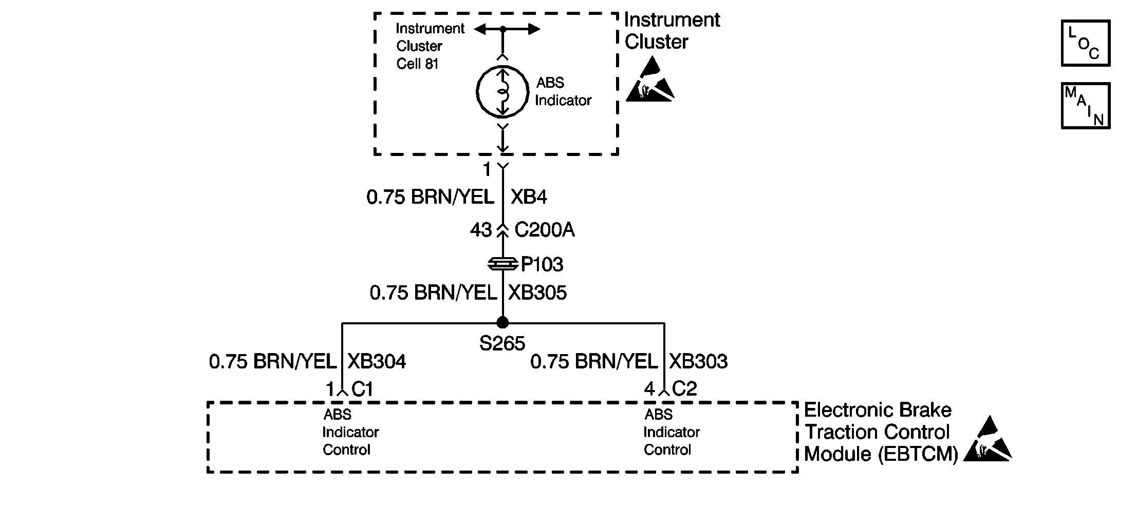
Circuit Description
This symptom table checks the state of the ABS indicator to identify a situation in which the driver could not be warned of a system malfunction by the ABS indicator. The EBTCM provides a ground through the ABS indicator control circuit to turn the ABS indicator on. If the control circuit is open or if the control circuit is shorted to voltage the ABS indicator will always be off. The EBTCM provides a redundant control circuit on the 4-pin connector C2, terminal 4 in the event that the 25-pin harness connector C1 becomes disconnected from the EBTCM. If this occurs, the ABS indicator will be turned on by a ground provided on the 4-pin connector C2, terminal 4.
Diagnostic Aids
The following can cause an intermittent malfunction:
| • | A poor connection can cause an intermittent malfunction. |
| • | Rubbed through wire insulation can cause an intermittent malfunction. |
| • | A wire that is broken inside the insulation can cause an intermittent malfunction. |
The ABS Indicator Lamp Test function of the scan tool may be used to command the indicator while looking for an intermittent malfunction in the ABS indicator circuitry.
Check for the following in any circuit suspected of causing an intermittent malfunction:
| • | Check for backed out terminals. |
| • | Check for improper mating. |
| • | Check for broken locks. |
| • | Check for improperly formed terminals. |
| • | Check for damaged terminals. |
| • | Check for poor terminal to wiring connections. |
| • | Check for physical damage to the wiring harness. |
Test Description
The number(s) below refer to the step numbers on the diagnostic table.
-
Running the scan tool Lamp Test will determine if the EBTCM can turn the indicator on and off.
-
If both EBTCM connectors C1 and C2 are not properly connected, the ABS indicator will be inoperative.
-
If other indicators in the instrument panel are not operating properly, there may be a concern with the instrument panel circuitry.
-
With terminal 1 of the EBTCM connector C1 grounded, the ABS indicator should come on.
-
This step checks for an open in the ABS indicator circuit.
-
This step checks for a short to voltage in the ABS indicator circuit.
Step | Action | Value(s) | Yes | No | ||||||||||||||||||
|---|---|---|---|---|---|---|---|---|---|---|---|---|---|---|---|---|---|---|---|---|---|---|
1 | Was the Diagnostic System Check performed? | -- | Go to A Diagnostic System Check | |||||||||||||||||||
Was the test completed successfully? | -- | |||||||||||||||||||||
3 |
Does the ABS indicator turn on then turn off? | -- | ||||||||||||||||||||
Does the ABS indicator turn on then turn off? | -- | Go to A Diagnostic System Check | ||||||||||||||||||||
Did the BRAKE indicator and the TC indicator turn on then turn off? | -- | Go to A Diagnostic System Check - Instrument Cluster in Instrument Panel, Gages and Console for diagnosis | ||||||||||||||||||||
6 |
Are the following signs evident:
| -- | ||||||||||||||||||||
7 |
Does the ABS indicator turn on and then turn off? | -- | ||||||||||||||||||||
Does the ABS indicator turn on? | -- | |||||||||||||||||||||
Is the resistance within the specified range? | 0-2 ohms | |||||||||||||||||||||
Is the voltage within the specified range? | 0-2 V | Go to A Diagnostic System Check - Instrument Cluster in Instrument Panel, Gages and Console for diagnosis | ||||||||||||||||||||
11 | Repair an open or a high resistance in the ABS indicator circuit. Refer to Wiring Repairs in Wiring Systems. Is the repair complete? | -- | Go to A Diagnostic System Check | -- | ||||||||||||||||||
12 | Repair a short to voltage in the ABS indicator circuit. Refer to Wiring Repairs in Wiring Systems. Is the repair complete? | -- | Go to A Diagnostic System Check | -- | ||||||||||||||||||
13 |
Is the repair complete? | -- | Go to A Diagnostic System Check | -- | ||||||||||||||||||
14 | Replace the EBTCM. Refer to EBTCM Replacement . Is the repair complete? | -- | Go to A Diagnostic System Check | -- | ||||||||||||||||||
15 | The malfunction is intermittent or the malfunction is not present at this time. Refer to Diagnostic Aids on the facing page for more information. Is the diagnosis complete? | -- | Go to A Diagnostic System Check | -- |
