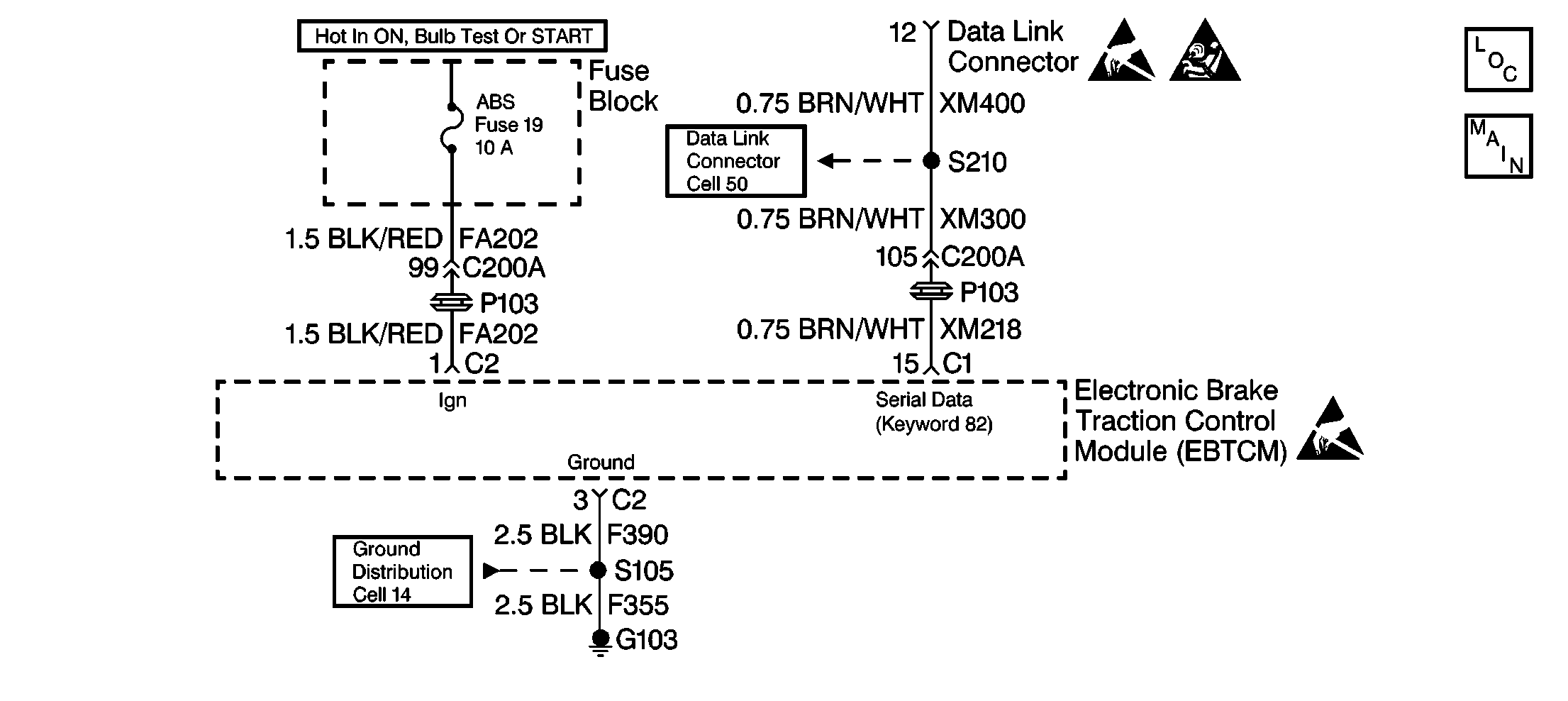
Circuit Description
The keyword 82 serial data line to the EBTCM is one of three communication protocols used by the various control modules on the vehicle. The primary function of the keyword 82 serial data line to the EBTCM is for diagnostic communication to the scan tool.
Diagnostic Aids
The following can cause an intermittent malfunction:
| • | A poor connection can cause an intermittent malfunction. |
| • | Rubbed through wire insulation can cause an intermittent malfunction. |
| • | A wire that is broken inside the insulation can cause an intermittent malfunction. |
Check for the following in any circuit suspected of causing an intermittent complaint:
| • | Check for backed out terminals. |
| • | Check for improper mating. |
| • | Check for broken locks. |
| • | Check for improperly formed terminals. |
| • | Check for damaged terminals. |
| • | Check for poor terminal to wiring connections. |
| • | Check for physical damage to the wiring harness. |
Test Description
The number(s) below refer to the step numbers on the diagnostic table.
-
If the scan tool cannot communicate with other modules on the serial data line, there is a concern with the serial data line circuit.
-
This step checks for an open or high resistance in the EBTCM ground circuit.
-
This step checks for an open or short to ground in the EBTCM ignition feed circuit.
-
This step checks for an open or high resistance in the Keyword 82 serial data line.
Step | Action | Value(s) | Yes | No |
|---|---|---|---|---|
1 | Was the Diagnostic System Check performed? | -- | Go toA Diagnostic System Check | |
Can the scan tool communicate with other modules on the Keyword 82 serial data line? | -- | Go to Data Link Communications System Check in Wiring Systems for diagnosis | ||
Is the resistance within the specified range? | 0-2 ohms | |||
Is the voltage measured equal to or greater than the specified voltage? | 10V | |||
Is the resistance within the specified range? | 0-2 ohms | |||
6 | Replace the EBTCM. Refer to EBTCM Replacement . Is the repair complete? | -- | Go to A Diagnostic System Check | -- |
7 | Repair an open or repair a high resistance in the EBTCM ground circuit. Refer to Wiring Repairs in Wiring Systems. Is the repair complete? | -- | Go to A Diagnostic System Check | -- |
8 | Repair an open or repair a short to ground in the ignition feed circuit. Refer to Wiring Repairs in Wiring Systems. Is the repair complete? | -- | Go to A Diagnostic System Check | -- |
9 | Repair an open or repair a high resistance in the Keyword 82 serial data line. Refer to Wiring Repairs in Wiring Systems. Is the repair complete? | -- | Go to A Diagnostic System Check | -- |
