Circuit Description
The Diagnostic System Check is an organized approach to identifying a condition created by an Antilock Brake System (ABS) or Traction Control System (TCS) malfunction. It must be the starting point for any ABS or ABS/TCS diagnosis because it directs the service technician to the next logical step in diagnosing the condition.
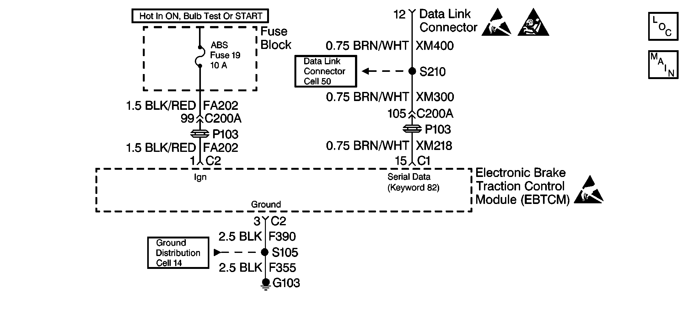
Serial data is exchanged by the EBTCM through connector C1 terminal 15. The EBTCM is supplied switched ignition voltage through connector C2 terminal 1. The EBTCM ground is provided through connector C2 terminal 3.
Diagnostic Process
Obtain a detailed description of when the condition occurred/occurs from the owner before beginning diagnosis on the ABS/TCS. This information may be useful in duplicating the condition. Perform a quick visual check of the following:
| • | Visually check all the connectors. |
| • | Visually check all the wiring. |
| • | Visually check all the wire routing. |
| • | Visually check all the retention. |
| • | Visually check all the system components. |
Many times the following can be the cause of the problem:
| • | A disconnected connector may cause the problem. |
| • | A loose connector may cause the problem. |
| • | An open fuse may cause the problem. |
| • | A misrouted wire may cause the problem. |
Perform the Diagnostic System Check if a visual inspection does not reveal an obvious problem. Refer to Diagnostic System Check in this section. ALWAYS start with the Diagnostic System Check table. This step is critical in quick and accurate diagnosis of any problem. Performing the Diagnostic System Check will direct you to the specific system area that has a problem and will verify that the diagnostic system is functioning properly. Correct system diagnosis cannot be ensured without starting diagnosis with the Diagnostic System Check.
Diagnostic Aids
Excessive resistance in the ground or switched ignition circuits will not allow communication with the EBTCM. If communication with the EBTCM is not possible, ensure the EBTCM ground connection is good and that there is no excessive resistance in the switched ignition supply circuit.
Test Description
The number(s) below refer to the step numbers on the diagnostic table.
-
Proper road testing is esential in this step to determine an ABS/TCS malfunction.
-
This step determines if there is a malfunctioning ABS indicator.
-
This step checks if the history DTC can be set as a current DTC.
Step | Action | Value(s) | Yes | No |
|---|---|---|---|---|
1 |
Does the scan tool communicate with the EBTCM? | -- | Go to No Communication with EBTCM | |
Are there any current diagnostic trouble codes? | -- | Go to the Applicable DTC Table | ||
Does the ABS indicator turn on for about 3 seconds then turn off? | -- | |||
4 |
Does the TC indicator turn on for about 3 seconds then turn off? | -- | ||
5 | Does the ABS indicator stay on? | -- | Go to ABS Indicator Always On | Go to ABS Indicator Inoperative |
6 | Does the TC indicator stay on? | -- | Go to Traction Control Indicator Always On | Go to Traction Control Indicator Inoperative |
7 | Are there any history DTC(s)? | -- | ||
Did the history DTC set as a current DTC while the vehicle was being driven? | -- | Go to the Applicable DTC Table | ||
9 | Did the vehicle's brakes exhibit any symptoms of improper operation that may be mechanical, and/or did the BRAKE warning indicator come on? | -- | Go to Brake Warning System Check in Hydraulic Brakes | System OK |
