Lower Steering Shaft, Lower Bearing, Column Jacket - Off Vehicle for Cadillac Catera 1997
Disassembly Procedure
- Remove the steering column housing; refer to Steering Column Housing - Off Vehicle .
- Remove the shaft assembly (1) from the steering column housing support and jacket assembly (2).
- Note the position of the lower steering shaft assembly (4) in relation to the upper steering shaft assembly (1).
- Mark (3) the upper steering shaft assembly (1) and mark (5) the lower steering shaft assembly (4) to show alignment.
- Remove the bearing assembly (2) from the steering column jacket assembly (1) if required.
- If required, remove the steering column housing support (2) from the steering column jacket assembly (3) in the following manner:
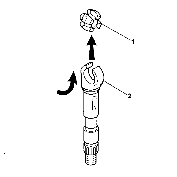
- Tilt the upper steering shaft assembly (2) 90 degrees from the lower steering shaft assembly (1).
- Disengage the upper steering shaft assembly (2) from the lower steering shaft assembly (1).
- Rotate the centering sphere (1) 90 degrees. Lift from the upper steering shaft assembly (2).
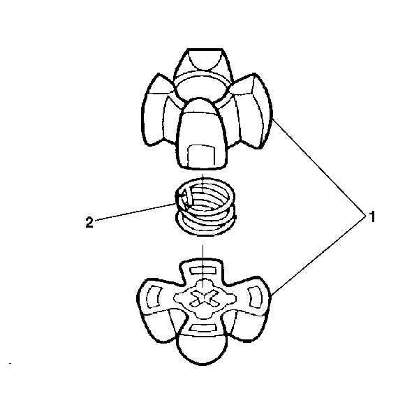
- Separate the centering sphere halves (1). Remove the joint preload spring (2).


Important: Failure to assemble properly will cause steering wheel to be turned 180 degrees.


| 6.1. | Remove the support screws (1). |
| 6.2. | Remove the steering column housing support (2). |

Assembly Procedure
Tools Required
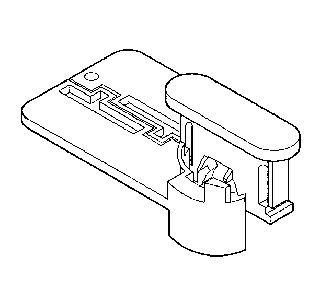
J 41688 Centering Sphere Installer
- Inspect the centering sphere (1) (3) for wear.
- Inspect the spring (2) for breakage. If either part is damaged, discard and replace with new part.
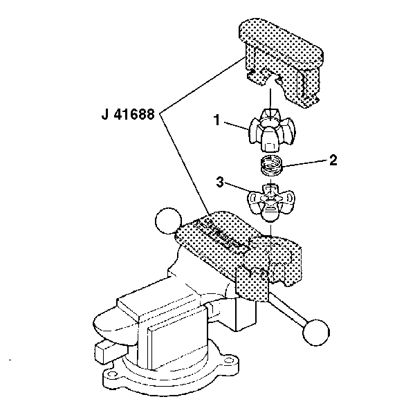
- Place the base of J 41688 in a vise.
- Apply lithium grease to the engagement areas of the centering sphere halves (1, 3).
- Place the lower centering sphere half (3), the joint preload spring (2), and the upper centering sphere half (1) into the base of J 41688 .
- Position the driver onto the upper centering sphere half.
- Compress the joint preload spring (2) and rotate J 41688 90 degrees clockwise.
- Install the upper steering shaft assembly (2) onto the centering sphere assembly (1) within the J 41688 .
- Rotate the upper steering shaft assembly (2) 90 degrees downward.
- Remove J 41688 from the vise.
- Separate the base and driver of J 41688 from the upper steering shaft assembly (2).
- Align the marks (3) made on the upper steering shaft assembly (1) with the marks (5) on lower steering shaft assembly (4) and install the lower steering shaft assembly (4) onto the centering sphere (2) within the upper steering shaft assembly (1).
- Rotate the upper steering shaft assembly (1) 90 degrees.
- Install the steering shaft assembly (1) into the steering column housing support (2).
- Install the bearing assembly (2) if required.
- Install the steering column housing support (2) as follows:
- To install the steering column housing, refer to Steering Column Housing - Off Vehicle .

Important: Ensure that the feet of the driver slide into the grooves of the tool base.

Notice: Use the correct fastener in the correct location. Replacement fasteners must be the correct part number for that application. Fasteners requiring replacement or fasteners requiring the use of thread locking compound or sealant are identified in the service procedure. Do not use paints, lubricants, or corrosion inhibitors on fasteners or fastener joint surfaces unless specified. These coatings affect fastener torque and joint clamping force and may damage the fastener. Use the correct tightening sequence and specifications when installing fasteners in order to avoid damage to parts and systems.
Tighten
Tighten the support screws (1) to 14.0-18.0 N·m.
| 16.2. | Position the steering column housing support (2) against the steering column jacket assembly (3). |
| 16.3. | Position the support screws (1) in the steering column housing support (2). |
Tighten
Tighten the support screws to 14.0-18.0 N·m.
