Side Door Opening Frame Replacement Door Frame Opening
Important: Sectioning should only take place in the recommended areas. Failure to do so may comprise the structural integrity of the vehicle.
The side door frame openings feature a unique modular build design to improve manufacturing quality. The side door frame openings are composed of numerous individual components which are pre-assembled.
The door frame is not available as a complete assembly. There are for service, however, individual assemblies available for sectioning the A-pillar, B-pillar, and C-pillar areas. The extent of the damage will determine the specific parts needed for sectioning.
General Sectioning Procedures for A-Pillar and C-Pillar Service Assemblies
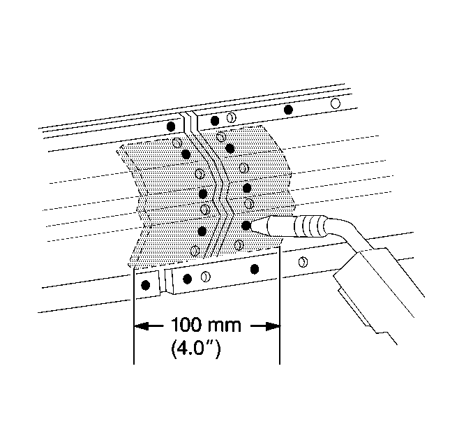
When sectioning the A-pillar or the C-pillar, install a 100 mm (4 inches) backing plate behind the joint, in order to ensure a solid and secure weld. Backing plates can be cut from the unused portion of the service part, or from the damaged section of the door frame.
Removal Procedure
- Remove all related panels and components.
- Visually inspect the damaged areas.
- Restore as much of the damage as possible to factory specifications.
- Remove the sealers, sound deadeners, and anticorrosion materials as necessary.
- Mark lines for cutting at the recommended sectioning locations.
- Cut the panels to be sectioned, taking care not to damage any inner panels.
- Locate all factory welds.
- Mark all factory welds.
- Drill out all necessary factory welds.
- Remove the damaged section of the door frame opening.
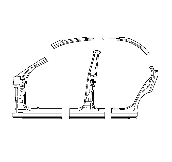
Important: Note the size and the location of the precut service assemblies. Only the A-pillar and the C-pillar have the flexibility to have other than factory cut locations. Select the specific areas to be sectioned based on the extent of damage to the door frame opening.
Important: Sectioning is recommended for the outer panel of the door frame opening. If any inner panels are damaged, they must be replaced at factory seams.
Important: Note the number and location of the welds for the installation of the service panel.
Installation Procedure
- Cut the service part to match the damaged section of the door frame opening.
- Remove the unused portion of the service part.
- Cut a 100 mm (4 inch) piece from the unused portion of the service part for a backing plate.
- Remove the flange on each side of the backing plate so that it will fit behind the sectioning joint.
- Drill 8 mm (0.31 inch) holes for plug welding in the service part in the locations noted from the original panel.
- Drill holes for plug welding along the sectioning cut on both the service part and the remaining original panel.
- Prepare the mating surfaces.
- Position the backing plates with 50 mm (2 inches) of the backing plate exposed.
- Plug weld as necessary.
- Position the service part to overlap the exposed 50 mm (2 inches) of the backing plate.
- Check fit of the service part using three-dimensional measurements as necessary.
- Plug weld the service part accordingly.
- Stitch weld along the sectioning joint of the service part.
- Make 25 mm (1 inch) welds along the seam with 25 mm (1 inch) gaps between.
- Complete the stitch weld. This will create a solid joint with minimal heat distortion.
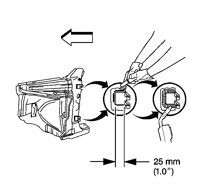
- Weld the base of the A-pillar hinge to the hinge pillar reinforcement.
- Use a cut-off wheel to cut 25 mm (1 inch) long cuts in the outer panel on three sides of the hinge, without cutting into the reinforcement.
- Check for proper location at the hinge using body dimensions.
- Stitch weld into these cuts for adequate penetration into the reinforcement.
- Clean and prepare welded surfaces.
- Prime with two-part catalyzed primer.
- Apply sealers and anti-corrosion materials as necessary.
- Install all the related panels and components.
Important: Trim the panels to achieve a gap of approximately 1.5 times the metal thickness at the sectioning joints.
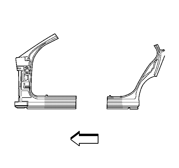
Important: The A-pillar is serviced with the hinge straps tack-welded in their proper locations.
Important: Alternate stitch welds as necessary to minimize heat distortion of the metal.
Make sure the weld penetrates and transfers to the inner hinge reinforcement to maintain the structural performance of the hinges.Important: Do not combine paint systems. Refer to paint manufacturer's recommendations.
Side Door Opening Frame Replacement B-Pillar Sectioning Procedure
Important: Sectioning should only take place in the recommended areas. Failure to do so may comprise the structural integrity of the vehicle.
The side door frame openings feature a unique modular build design to improve manufacturing quality. The side door frame openings are composed of numerous individual components which are pre-assembled.
The door frame is not available as a complete assembly. There are for service, however, individual assemblies available for sectioning the A-pillar, B-pillar, and C-pillar areas. The extent of the damage will determine the specific parts needed for sectioning.
B-Pillar Sectioning Procedure
When you section the B-pillar, note the size and location of the pre-cut service panel. Don't section the hinge reinforcement panel. Don't use the hinge reinforcement panel do make backing plates. If damage requires replacement of the inner door frame reinforcement, it is available separately for service.
Removal Procedure
- Remove all related panels and components.
- Visually inspect the damaged areas.
- Restore as much of the damage as possible to factory specifications.
- Remove sealers, sound deadeners, and anti-corrosion materials as necessary.
- Mark lines for cutting at the recommended sectioning locations.
- From inside the vehicle at the upper area of the inner reinforcement, measure from the attachment seam 318 mm (12.63 inches) rearward. Mark and cut as necessary.
- Locate the welds attaching the inner reinforcement to the roof rail.
- Mark the welds attaching the inner reinforcement the roof rail.
- Drill out the welds attaching the inner reinforcement to the roof rail.
- Drill out the welds down the length of the B-pillar inner reinforcement.
- Locate the remaining welds attaching the hinge reinforcement to the roof rail and the B-pillar outer.
- Mark the welds.
- Drill out the welds.
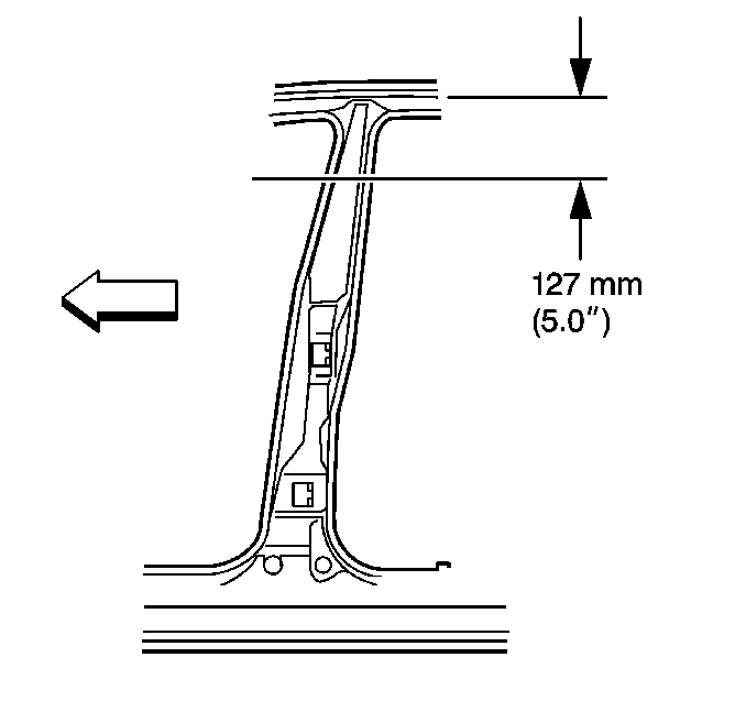
- Measure and mark downward from the bottom of the roof drip rail 127 mm (5 inches).
- Cut the upper portion of the outer B-pillar to remove the damage pillar.
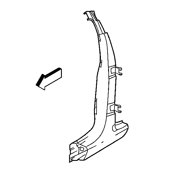
Important: Note the size and the location of the precut service assembly. Cut at the recommended rocker panel locations. Ensure you don't cut the inner reinforcements.
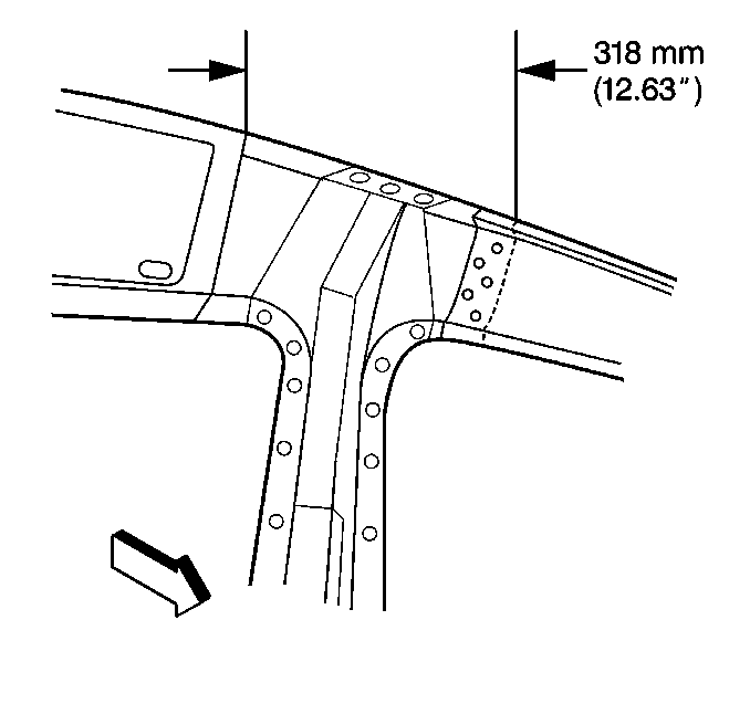
Important: The inner reinforcement should lay inward for access to the B-pillar hinge reinforcement. Both the inner reinforcement and the B-pillar hinge reinforcement attache to the roof rail.

Installation Procedure
- Cut a 100 mm (4 inches) from the damaged portion of the B-pillar for a backing plate. It may be necessary to fabricate a backing plate.
- Remove the flange on each side of the backing plate so that it will fit behind the sectioning joint.
- Drill 8 mm (0.31 inch) holes for plug welding in the service panel.
- Drill holes for plug welding along the sectioning cut on both the service part and the remaining original panel.
- Prepare the mating surfaces.
- Position the backing plates with 50 mm (2 inches) of the backing plate exposed.
- Plug weld the backing plate as necessary.
- The top of the B-pillar service assembly is cut at the recommended location.
- Prepare mating surfaces.
- Position the service part to overlap the exposed 50 mm (2 inches) of the backing plate).
- Check fit using three-dimensional measurements.
- Clamp the B-pillar inner reinforcement in place.
- Release the clamp on the inner reinforcement, allowing it to lay inward.
- Drill 8 mm (0.31 inch) holes for plug welding through the hinge reinforcement.
- Re-check fit of the B-pillar service assembly by using three dimensional measuring.
- From inside the vehicle, weld the hinge reinforcement to the roof rail.
- Position the inner reinforcement.
- Weld the inner reinforcement accordingly.
- Complete the welding at the rocker and the upper B-pillar sectioning joints.
- Stitch weld along the sectioning joints.
- Make 25 mm (1 inch) welds along the seam with 25 mm (1 inch) gaps between.
- Complete the stitch weld. This will create a solid joint with minimal heat distortion.
- Use a cut-off wheel to cut 25 mm (1 inch) long cuts in the outer panel on three sides of the hinge, without cutting into the reinforcement.
- Use the body dimensions as necessary in order to check for the proper location of the hinge.
- Stitch weld into these cuts for adequate penetration into the reinforcement.
- Complete all other welds and sectioning procedures as necessary.
- Clean and prepare welded surfaces.
- Prime with two-part catalyzed primer.
- Apply sealers and anti-corrosion materials as necessary.
- Install all related panels and components.
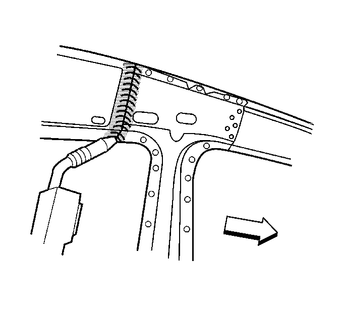
Important: The B-pillar service assembly may require some grinding for proper fit.
Important: Use the inner reinforcement as a template. This will allow welding completely through the inner panels, which should maintain the structural performance of the B-pillar.
Important: Do not drill through the outer panel.
Important: A 50 mm (2 inch) backing plate is recommended to prevent weld burn through.

Important: In addition, the B-pillar is serviced with the hinge straps that are tack welded in their proper location. It is necessary to weld the base of the hinge to the hinge reinforcement.
Make sure the weld penetrates and transfers to the inner hinge reinforcement to maintain the structural performance of the hinges.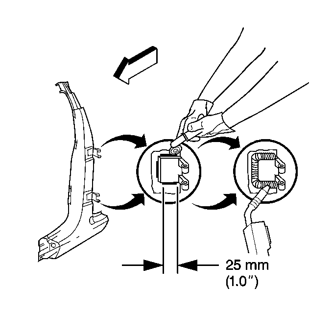
Important: Alternate stitch welds as necessary in order to minimize heat distortion of the metal.
Important: Do not combine paint systems. Refer to paint manufacturer's recommendations.
