GM Service Manual Online
For 1990-2009 cars only

Info - 4L30-E Automatic Transmission Service Policy Procedure

Subject:4L30-E Automatic Transmission Service Policy Procedure

Models:1997-2001 Cadillac Catera
With 4L30E Automatic Transmission


This bulletin is being revised to correct a statement in the Fluid Checking Procedure after SRTA installation. The word "not" is being deleted for content accuracy. Please discard Corporate Bulletin Number 01-07-30-033.


This bulletin covers the service policy for Cadillac Catera vehicles equipped with the 4L30E Automatic Transmission when repairs are being performed under warranty. This bulletin does not apply to out of warranty repairs. The only service options available are listed below.

The service policy permits limited on-vehicle service repairs or Goodwrench® Service Replacement Transmission Assemblies (SRTA) only. Goodwrench® SRTA transmissions and limited service parts can be ordered from General Motors Service Parts Operations.

Transmission Pre-Delivery Inspection

TRANSMISSION FLUID LEVEL CHECK DURING THE PRE-DELIVERY INSPECTION IS NOT NECESSARY UNLESS A FLUID LEAK OR PERFORMANCE CONCERN HAS BEEN DETECTED. THE TRANSMISSION FLUID LEVEL IS SET AT THE FACTORY PRIOR TO SHIPMENT OF THE VEHICLE.

Transmission Maintenance

The 4L30E automatic transmission requires no maintenance, oil level check and/or oil change under normal operating conditions. Under severe conditions (taxi, police, delivery service, repeated trailer towing, hilly or mountainous terrain, or city traffic with high 32°C (90°F) ambient temperature), both the fluid and the filter should be changed at 80,000 km (50,000 mi) intervals.

In Dealership Limited Repair Policy

On-Vehicle Service Parts
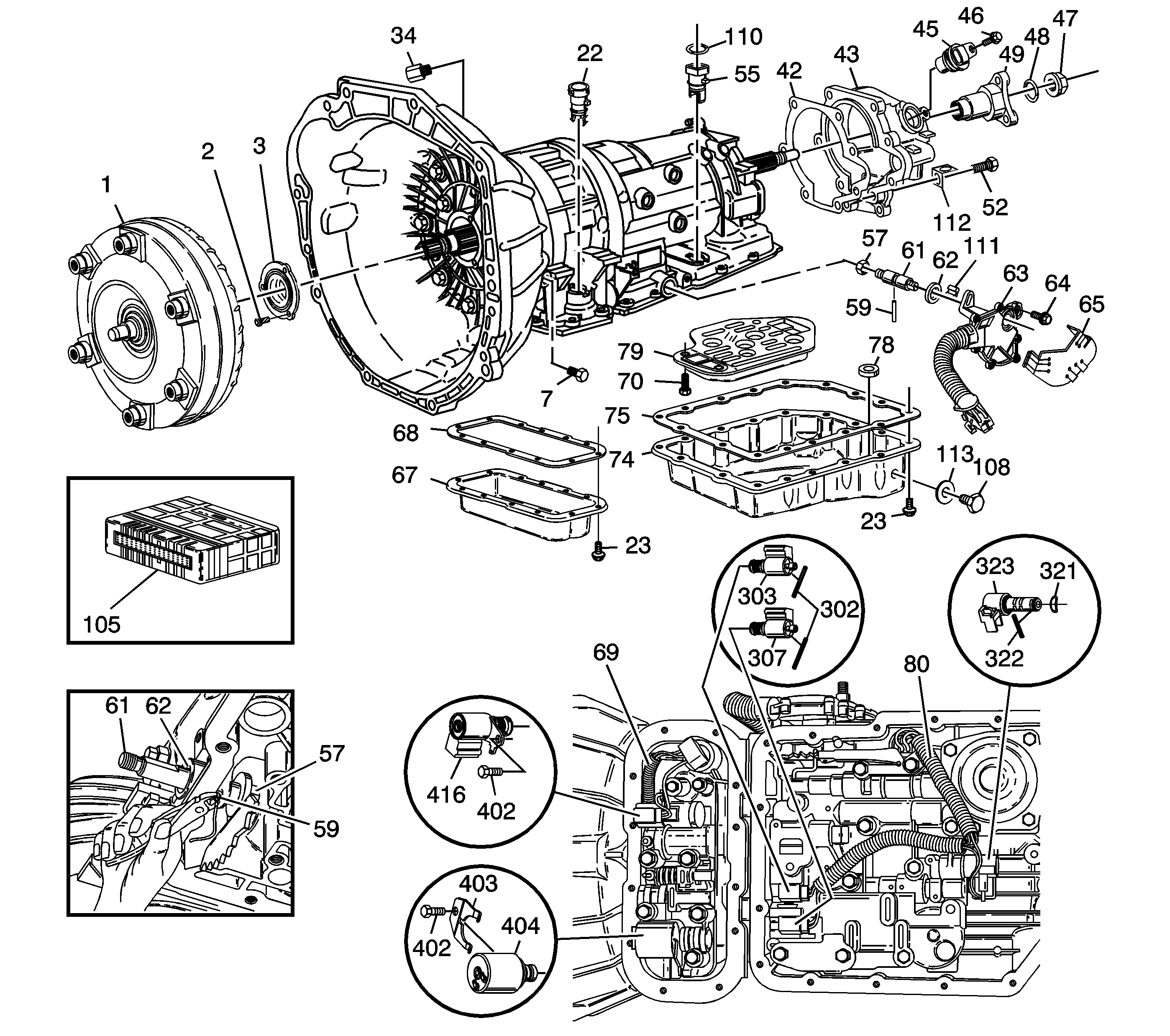

Object Number: 820653  Size: LF
(1)Torque Converter Clutch Assembly
(2)Seal Assembly Screw
(3)Converter Housing Seal Assembly
(7)Converter Housing Plug
(22)Adapter Case Electrical Connector
(23)Oil Pan Screw
(23)Oil Pan Screw
(34)Cooler Fitting
(42)Extension Case Gasket
(43)Extension Assembly
(45)Speed Sensor Assembly
(46)Speed Sensor Screw
(47)Output Shaft/Drive Flange Nut
(48)Drive Flange Seal
(49)Drive Flange
(52)Extension/Main Case Screw
(55)Main Case Electrical Connector
(57)Detent Lever Nut
(59)Spring Pin
(59)Spring Pin
(61)Manual Shaft
(61)Manual Shaft
(62)Manual Shaft Seal
(63)Mode Switch Assembly
(64)Mode Switch Bolt
(65)Mode Switch Shield
(67)Adapter Case Oil Pan
(68)Adapter Case Oil Pan Gasket
(69)Adapter Case Harness Assembly
(70)Valve Body/Main Case Screw
(74)Main Case Oil Pan
(75)Main Case Oil Pan Gasket
(78)Chip Collector Magnet
(79)Oil Filter
(80)Main Case Harness Assembly
(105)Transmission Control Module
(108)Fill Screw
(110)O-Ring Seal
(111)Mode Switch Bracket
(112)Bracket
(113)Fill Screw Seal
(302)Spring Pin
(303)1-2 and 3-4 Shift Solenoid Assembly
(307)2-3 Shift Solenoid Assembly
(321)PWM Solenoid Waved Washer
(322)PWM Solenoid Pin
(323)Band Control PWM Solenoid Assembly
(402)Pressure Control and TCC Solenoid Screw
(403)Pressure Control Solenoid Retainer
(404)Pressure Control Solenoid
(416)Torque Converter Clutch Solenoid

The limited on-vehicle repairs which may be performed are shown above. Parts needed for these repairs can be ordered from General Motors Service Parts Operations.

4L30E Quick Check Procedure

  1. Record the customer concern on the repair order.
  2. Use the Tech 2 scan tool to check for diagnostic trouble codes (DTC).
  3. If there is a stored transmission code, refer to SI2000 or the printed Service Information for the specific DTC.

  4. Test drive the vehicle. Monitor the powertrain with the Tech 2 or a suitable scan tool.
  5. Were any DTCs set? If new DTCs were set, refer to SI2000 or the printed Service Information for the specific DTC. Correct all codes before continuing.
  6. For a poor performance condition, verify engine performance. If engine performance is good, refer to the torque converter evaluation in SI2000 or the printed Service Information.
  7. If all of the above steps do not lead to a concern correction and the transmission still does not function correctly, refer to SI2000 or the printed service information for further diagnosis information. If the diagnosis information determines that an internal component of the transmission needs to be serviced, do not disassemble the transmission; replace the transmission.

Transmission Oil Cooler Flushing

Notice: If the oil cooler and lines are not flushed and emptied of transmission fluid prior to the installation of a Goodwrench® SRTA, the transmission fluid level may be excessive and transmission damage could occur.

Oil cooler flushing and an oil cooler flow check must be performed whenever a transmission is removed for service. It is essential to flush the cooler prior to a Goodwrench® SRTA installation or when fluid contamination is suspected. Use Kent-Moore Tool J 35944-A and solvent J 35944-22 to flush the cooler. Instructions may be found in SI2000 and in the Service Manual in the On-Vehicle Service section. The time needed to flush the cooler is included in labor operation K7000 (Transmission Assembly Replace) for flushing of the cooler and the lines.

Transmission Fluid Level Checking Procedure

Checking of the fluid level is required after an SRTA installation or when any on-vehicle service procedure has been performed. The correct fluid level checking procedure is as follows:

  1. Warm the transmission to normal operating temperature. This can be done two different ways.
  2. • Drive the vehicle 24 km (15 mi).
    • Run the engine until the transmission fluid temperature has reached 45-85°C  (113-185°F).
  3. Raise the vehicle on a hoist and insure the vehicle is level.
  4. Start the engine before removing the transmission oil level/fill plug.
  5. Caution: 

       •  The transmission fluid is now warm, 45-85°C (113-185°F). Take proper service precautions to avoid injury from warm fluid.
       • Do not turn the engine off with the fill plug removed. When the engine is shut off, hot fluid will be expelled from the fill plug opening and you may be injured by the hot fluid.

    Important: The engine must be running when the transmission fluid fill plug is removed or excessive fluid loss will occur. Since the actual fluid level is unknown, have a container ready to capture any lost fluid and stand clear when removing the fill plug.

    Important: To prevent fluid leaks and the need for repeat repairs, the fill plug seal must be replaced each time the fill plug is removed.

  6. With the engine running and the transmission fluid at normal operating temperature, remove the transmission fill plug. The fluid level should be even with the bottom of the threaded opening in the transmission oil pan. If the level is low, add only enough Dexron®-III automatic transmission fluid to bring the fluid level to the bottom of the threaded opening in the transmission oil pan.
  7. Reinstall the fill plug.
  8. Tighten
    Tighten the fill plug to 45 N·m(33 lb ft).

  9. Inspect for external leaks. If a leak is found, refer to Automatic Transmission for the 4L30E, Fluid Leak Diagnosis, Document ID Number 405612, in SI2000. Refer to Diagnostic Information and Procedures, Fluid Leak Diagnosis, in the Automatic Transmission sub-section of the appropriate Service Manual.

Parts Information

A Goodwrench® SRTA (Service Replacement Transmission Assembly) should be used when any repair cannot be completed by the replacement of the parts shown in the previous portion of this bulletin.

Refer to the appropriate GMSPO Parts Catalog for the correct part numbers based on the application. The transmission identification information will assist in selecting the correct service replacement parts or the Goodwrench® Service Replacement Transmission Assembly (SRTA) unit to order from GMSPO.

Hydra-matic 4L30-E Transmission Identification Information


Object Number: 820652  Size: LF
(1)Transmission I.D. Location
(2)Production Identification Tag
(3)Model
(4)Part Number
(5)Serial Number
(6)TCM Code
(7)Calibration
(8)Remanufacturing Identification Tag
(9)Model
(10)Part Number
(11)Serial Number
(12)Build Date (Week)
(13)R+Build Date (Year)