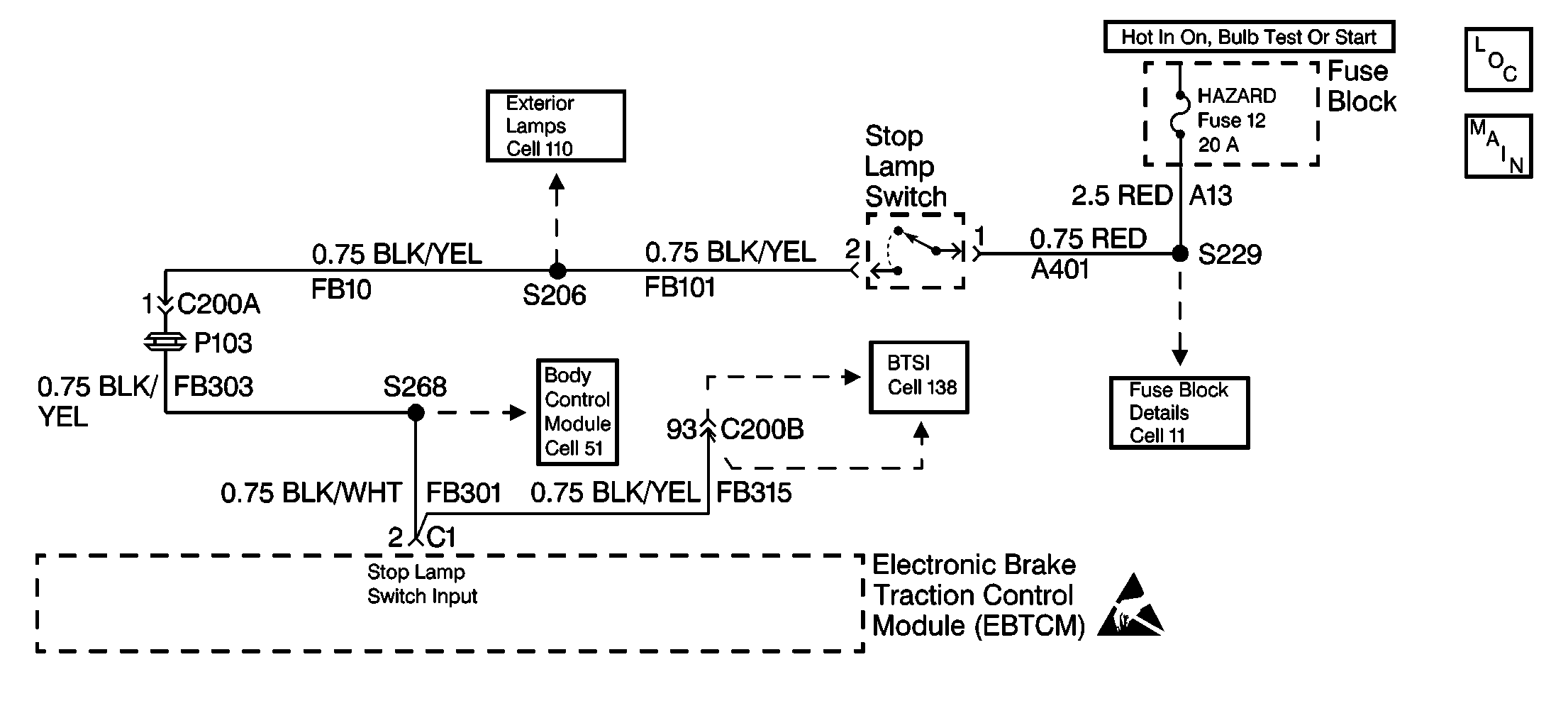
Circuit Description
The brake lamp switch circuit is an input to the EBTCM. It is used to monitor the status of the brake lamp switch. This is important because ABS is activated and TCS is inhibited when the brake switch is on and ABS is inhibited when the brake switch is off.
Conditions for Setting the DTC
| • | There is an open in the brake lamp switch circuit. |
| • | Both the left and the right brake lamp bulbs are open. |
| • | There is a misadjusted or a malfunctioning brake lamp switch. |
| • | There is a malfunction in the EBTCM. |
Action Taken When the DTC Sets
| • | A malfunction DTC is stored. |
| • | The ABS and the TC indicator lamps are turned on. |
| • | The ABS and the TCS are disabled. |
Conditions for Clearing the DTC
| • | The condition for the DTC is no longer present. |
| • | The scan tool Clear DTCs function is used. |
| • | 100 drive cycles have passed with no DTCs detected. |
Diagnostic Aids
Perform a thorough inspection of the wiring. Perform a thorough inspection of the connectors. Failure to carefully and fully inspect the wiring and the connectors may result in misdiagnosis. Misdiagnosis causes part replacement with reappearance of the malfunction.
Test Description
The number(s) below refer to the step number(s) on the diagnostic table.
-
If the brake lamps operate properly, the integrity of the circuit up to splice S206 is verified.
-
This step verifies if the brake switch input is being received by the EBTCM.
-
If both brake lamp bulbs are not open, the malfunction is between splice S206 and the clamp cruise fuse 15, or is an open fuse.
Step | Action | Value(s) | Yes | No | ||||||||||||
|---|---|---|---|---|---|---|---|---|---|---|---|---|---|---|---|---|
1 | Was the Diagnostic System Check performed? | -- | Go to A Diagnostic System Check | |||||||||||||
Have an assistant observe the rear brake lamps while applying pressure to the brake pedal. Are the brake lamps on? | -- | |||||||||||||||
Does the scan tool indicate the brake lamp switch applied within 25.5 mm (1 in) of travel? | -- | |||||||||||||||
Is the left brake lamp bulb and the right brake lamp bulb open? | -- | |||||||||||||||
5 |
Is the voltage equal to or greater than the specified voltage? | 10 V | ||||||||||||||
6 |
Are the following signs evident:
| -- | ||||||||||||||
7 |
Did DTC 37 reset? | -- | Go to A Diagnostic System Check | |||||||||||||
8 | Use a J 39200 DMM to measure the voltage between the brake lamp switch terminal 1 and ground. Is the voltage equal to or greater than the specified voltage? | 10 V | ||||||||||||||
9 | While applying firm pressure on the brake pedal use a J 39200 DMM to measure the voltage between the brake lamp switch terminal 2 and ground. Is the voltage equal to or greater than the specified voltage? | 10 V | ||||||||||||||
10 | Repair an open in the circuit between 20 A HAZARD fuse 12 and the brake lamp switch. Refer to Wiring Repairs in Wiring Systems. Replace the 20 A fuse 12 if fuse is open. Is the repair complete? | -- | Go to A Diagnostic System Check | -- | ||||||||||||
11 | The brake lamp switch is misadjusted or has open contacts. Readjust or replace the brake lamp switch as necessary. Refer to Stoplamp Switch Replacement in Hydraulic Brakes. Is the repair complete? | -- | Go to A Diagnostic System Check | -- | ||||||||||||
12 | Repair an open in the circuit between the brake lamp switch and the EBTCM. Refer to Wiring Repairs in Wiring Systems. Is the repair complete? | -- | Go to A Diagnostic System Check | -- | ||||||||||||
13 | Replace the EBTCM. Refer to EBTCM Replacement . Is the repair complete? | -- | Go to A Diagnostic System Check | -- | ||||||||||||
14 | Replace both of the brake lamp bulbs. Refer to Tail Lamp Bulb Replacement in Lighting Systems. Is the repair complete? | -- | Go to A Diagnostic System Check | -- | ||||||||||||
15 | Repair an open between splice S206 and the EBTCM. Refer to Wiring Repairs in Wiring Systems. Is the repair complete? | -- | Go to A Diagnostic System Check | -- | ||||||||||||
16 | Replace all the terminals or replace the connector that exhibits the following signs:
Refer to Connector Repairs or Repairing Connector Terminals in Wiring Systems. Is the repair complete? | -- | Go to A Diagnostic System Check | -- |
