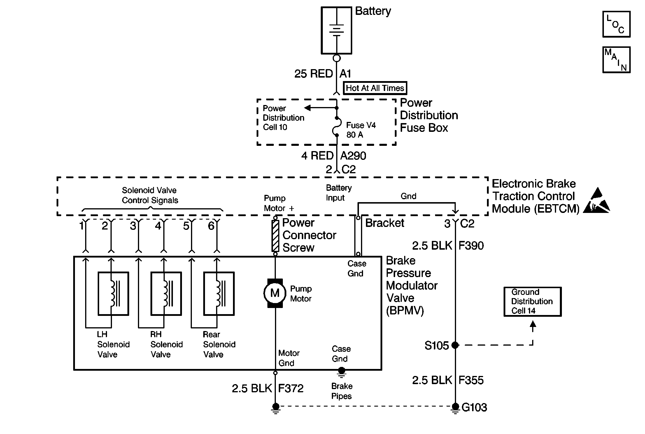
Circuit Description
The pump motor relay closes and provides voltage to operate the pump when it is grounded by the EBTCM. Once the motor circuit is energized a pump on signal is sensed by the EBTCM to verify pump operation.
Conditions for Setting the DTC
| • | Voltage is present at the pump motor for 5 seconds without pump motor relay activation from the EBTCM. |
| • | Voltage is NOT present at the pump motor within 60 milliseconds after the EBTCM requests pump motor relay activation. |
| • | The pump motor runs for longer than 100 milliseconds after the EBTCM requests pump motor cancellation. |
| • | The motor GND circuit is open. |
| • | There is a pump motor malfunction. |
Action Taken When the DTC Sets
| • | A malfunction DTC is stored. |
| • | The ABS and the TC indicator lamps are turned on. |
| • | The ABS and the TCS are disabled. |
Conditions for Clearing the DTC
| • | The condition for DTC is no longer present. |
| • | The scan tool Clear DTCs function is used. |
| • | 100 drive cycles have passed with no DTCs detected. |
Diagnostic Aids
The Return Pump Relay Test, located in Special Functions of the scan tool can be used to determine if the pump circuit is operating properly. This test can only be performed if DTC 35 is not currently set.
Perform a thorough inspection of the wiring. Perform a thorough inspection of the connectors. Failure to carefully and fully inspect the wiring and the connectors may result in misdiagnosis. Misdiagnosis causes part replacement with reappearance of the malfunction.
Test Description
The number(s) below refer to the step number(s) on the diagnostic table.
-
This step checks for a short to ground on the EBTCM side of the fuse. Check both fuse block terminals to verify. The fuse terminals are not identified.
-
This step checks if the fuse opens when the ignition switch is turned to the RUN position, and the ABS/TCS performs the self test during the test drive.
-
This step determines if a short to ground in the pump is causing the open fuse. If the pump checks OK, the short is in the EBTCM.
-
If the pump is running constantly in this step, the pump relay contacts are stuck closed.
Step | Action | Value(s) | Yes | No | ||||||||||||
|---|---|---|---|---|---|---|---|---|---|---|---|---|---|---|---|---|
|
Important: Perform the following checks before testing:
| ||||||||||||||||
1 | Was the Diagnostic System Check performed? | -- | Go to A Diagnostic System Check | |||||||||||||
2 |
Is the fuse open? | -- | ||||||||||||||
3 | Use a J 39200 DMM to measure the resistance between the pump motor ground stud and ground. Is the resistance within the specified range? | 0-5 ohms | ||||||||||||||
Use a J 39200 DMM to measure the resistance between both of the pump distribution fuse block terminals of the MaxiFuse® V4 and ground. Is the resistance within the specified range on either terminal? | OL (Infinite) | |||||||||||||||
5 |
Is the voltage within the specified range? | Battery Voltage | ||||||||||||||
6 |
Is the resistance within the specified range? | OL (Infinite) | ||||||||||||||
Is the MaxiFuse® open? | -- | Go to A Diagnostic System Check | ||||||||||||||
Is the resistance within the specified range? | OL (Infinite) | |||||||||||||||
9 |
Are the following signs evident:
| -- | ||||||||||||||
10 |
Is the resistance within the specified range? | 0.05-10 ohms | ||||||||||||||
Is the pump running constantly? | -- | |||||||||||||||
12 |
Did DTC 35 reset? | -- | Go to A Diagnostic System Check | |||||||||||||
13 | Replace the EBTCM. Refer to EBTCM Replacement . Is the repair complete? | -- | Go to A Diagnostic System Check | -- | ||||||||||||
14 | Replace the BPMV. Refer to Brake Pressure Modulator Valve (BPMV) Replacement . Is the repair complete? | -- | Go to A Diagnostic System Check | -- | ||||||||||||
15 | Repair an open in CKT A290. Refer to Wiring Repairs in Wiring Systems. Is the repair complete? | -- | Go to A Diagnostic System Check | -- | ||||||||||||
16 | Repair a short to ground in CKT A290. Refer to Wiring Repairs in Wiring Systems. Is the repair complete? | -- | Go to A Diagnostic System Check | -- | ||||||||||||
17 | Repair an open or a loose connection in CKT F372. Refer to Wiring Repairs in Wiring Systems. Is the repair complete? | -- | Go to A Diagnostic System Check | -- | ||||||||||||
18 | Replace all the terminals or replace the connector that exhibits the following signs:
Refer to Connector Repairs or Repairing Connector Terminals in Wiring Systems. Is the repair complete? | -- | Go to A Diagnostic System Check | -- | ||||||||||||
