FUEL PUMP/FUEL SUPPLY LINE ADDITIONAL PARTS

1982 CIMARRON - FUEL PUMP REPLACEMENT PROCEDURE
1982 Cimarrons were built using two styles of fuel pumps, each style requiring a specific fuel supply line. This bulletin outlines a service procedure which should be followed when servicing or replacing a 1982 Cimarron fuel pump.
1. Identify the fuel pump originally installed in the vehicle.
A. Early built vehicles were equipped with a fuel pump (P/N 6441568) which is stamped with the number 41568. This pump has the inlet nipple which points to the rear of the vehicle.
B. Later production vehicles are equipped with an updated fuel pump (P/N 6471941) which is stamped with the number 42023. This pump has the inlet nipple which points to the right side of the vehicle and is released as the service fuel pump through GMWDD.
2. If the vehicle being serviced has the late fuel pump (stamped 42023), no modifications to the fuel lines are required. On these vehicles, follow the 1982 Cimarron Service Information Manual procedure for pump removal, installation, and feed hose clamp orientation.
3. When installing a service fuel pump (stamped 42023) in a vehicle originally equipped with an early design pump (stamped 41568), the listed fuel line modifications must be performed.
A. Install a new fuel feed rubber hose (P/N 14046399).
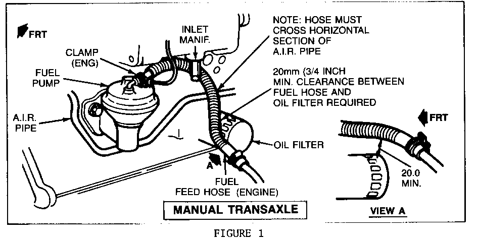
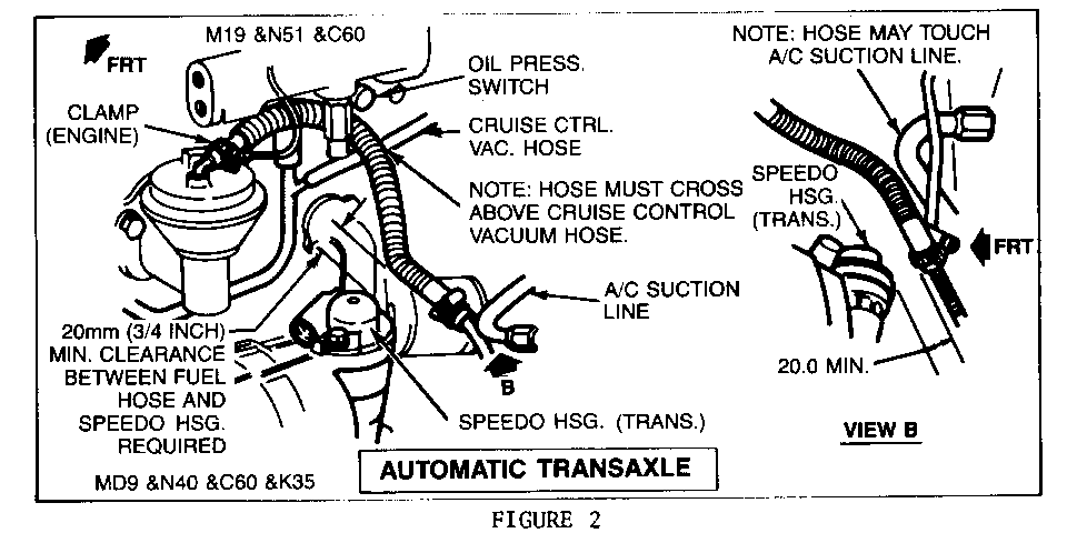
B. Once the new pump and feed hose have been installed, it will be necessary to bend the fuel feed pipe to obtain the proper clearance.
1. Manual Transaxle vehicles require a 20mm (3/4 inch) clearance between the fuel feed hose and the oil filter (refer to Figure 1).
2. Automatic Transaxle vehicles require a 20mm (3/4 inch) clearance between the fuel feed hose and the transmission speedometer housing (refer to Figure 2).
The above mentioned clearances are mandatory to assure optimum component life.
4. When servicing the fuel inlet filter at the carburetor, care should be taken on reassembly of the fuel supply line to the carburetor. Proceed as follows:
A. Finger tighten the tube nut.
B. Tube to rubber hose joint are to be in the same plane, parallel to rocker cover or cylinder head surface.
C. Once this alignment has been established, retain the fuel pipe from rotating while torquing tube nut. Torque tube nut to 20-30 N.m (12-22 ft. lbs.).
D. The folloving components make up the fuel supply line:
Service Name Part No. ---- -------- Hose, Carburetor Fuel Inlet 14055043
Pipe Assembly, Fuel Pump Outlet 14058907
Pipe Assembly Carburetor Inlet 14058908


General Motors bulletins are intended for use by professional technicians, not a "do-it-yourselfer". They are written to inform those technicians of conditions that may occur on some vehicles, or to provide information that could assist in the proper service of a vehicle. Properly trained technicians have the equipment, tools, safety instructions and know-how to do a job properly and safely. If a condition is described, do not assume that the bulletin applies to your vehicle, or that your vehicle will have that condition. See a General Motors dealer servicing your brand of General Motors vehicle for information on whether your vehicle may benefit from the information.
