ON CAR CONTROL VALVE ASSEMBLY R & R

THM 325-4L, 200-4R AND 125C TRANSMISSIONS ON CAR CONTROL VALVE ASSEMBLY R&I
This bulletin provides service procedures for on car removal and installation of transmission control valve assemblies not covered in Cadillac Service Information Manuals. Correct placement of the control valve assembly's check balls is essential to proper transmission operation and is also furnished in this bulletin.
Based on model application, refer to the following chart to determine which service procedure to utilize:
Transmission Model Refer To ------------ -------- THM 325-4L Section I of Bulletin
THM 200-4R Section II of Bulletin
THM 125C 1983 Service Information Manual, Cimarron Section, pages 7A-17 through 7A-19
I. 1982 or 1983 THM 325-4L Transmission ------------------------------------
Removal:
1. Remove transmission oil pan and gasket.
2. Remove transmission oil filter and its "O" ring.
3. Disconnect wire leads at case electrical connector and pressure switch(es). Remove D-2 signal, reverse signal and overrun pipe retainers and pipes.
4. Remove throttle lever and bracket assembly.
5. Remove all remaining control valve assembly attaching bolts.
6. Disconnect manual valve in order to remove control valve assembly from transmission. Use care to not drop manual valve as damage may occur.
7. Remove control valve assembly and its gasket. One check ball (#12) is located between valve body and gasket.
8. Remove TCC solenoid assembly attaching bolts, solenoid and "O" ring seal.
9. Remove 1-2, 3-4 accumulator assembly attaching bolts, housing, accumulator housing gasket and 1-2 accumulator spring. The Drive 3 (D3) check ball (#11) will be in the accumulator housing.
10. At this point, the spacer plate will not be attached to the case. Use care when removing the spacer plate from transmission case as there will be nine check balls on top.
11. Install two guide pins into case as shown in Figure 22, page 325-4L-14, in the 1983 Service Information Manual.
Installation:
1. Orient and install a new case to spacer plate gasket marked "C" (from P/N 8635919 kit) on top of spacer plate.
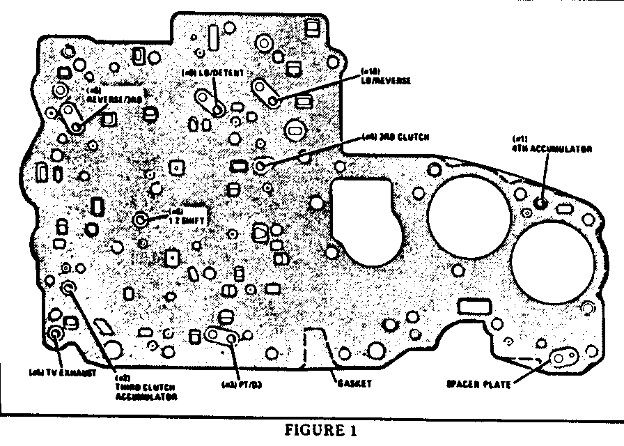
2. Properly position nine (9) check balls (#1 through #10 except #7 which is in the case cover) on spacer plate (refer to Figure #1). Retain check balls in place with petrolatum.
3. Install spacer plate on transmission and retain temporarily using a small bolt from the accumulator housing. Install bolt in any bolt hole near the center of the spacer plate.
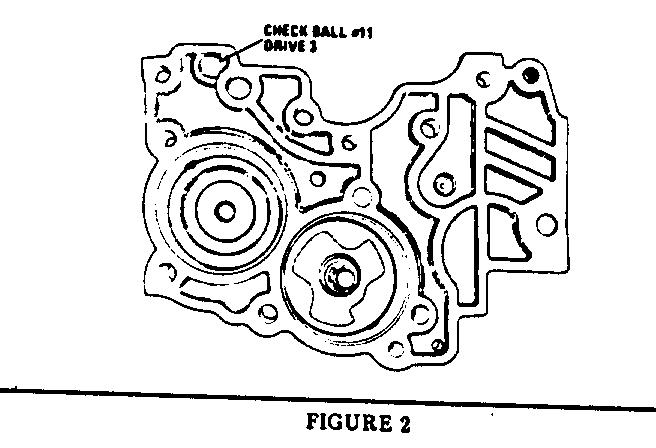
4. Position a check ball (#11) in accumulator housing (refer to Figure #2).
5. Place a new gasket (from P/N 8635919 kit) onto the accumulator housing and position housing onto transmission. Temporarily hold in place with two of the appropriate bolts. Do not torque at this time.
6. Install TCC solenoid with a new "O" ring (P/N 8630052) in its proper location on accumulator housing. Finger tighten two attaching bolts to hold solenoid and wiring harness in place. The small bolt that was used to temporarily hold the spacer plate in place (step #3 above) can now be removed.
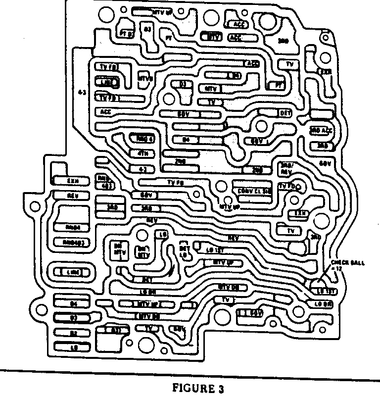
7. Position a check ball (#12) in control valve assembly (refer to Figure #3).
8. Place a new control valve to spacer plate gasket marked "VB" (from P/N 8635919 kit) on top of control valve assembly.
9. Install control valve assembly to case using two guide pins as locators. Start two attaching bolts to hold in place.
10. Install manual valve link into valve (it may be necessary to remove the push on nut to install the link).
11. Install throttle lever and bracket assembly.
12. Install all oil pipes, wiring and remaining control valve to case and accumulator housing to case attaching bolts; torque all these bolts to 15 N.m (10 ft. lbs.). Refer to page 325-4L-65, step 14, of the 1983 Service Information Manual for installation of oil pipes and wirirg.
13. Clean, air dry, inspect (and if necessary replace) oil filter assembly with a new "O" ring (P/N 1363951).
14. Clean, inspect and install transmission oil pan with a new gasket (P/N 8635014). Torque all these bolts to 16 N.m (12 ft. lbs.).
II. 1981,1982 or 1983 THM 200-4R Transmissions ------------------------------------------ Removal:
1. Remove transmission oil Pan and gasket (RTV).
2. Remove transmission oil filter and its "O" ring.
3. Disconnect wire leads at electrical connector.
4. Remove TCC solenoid assembly attaching bolts, clips,"O" ring and solenoid.
5. Remove throttle lever and bracket assembly.
6. Remove manual detent roller and spring assembly, signal oil pipe retaining clip and signal oil pipe.
7. Remove remaining control valve assembly attaching bolts.
8. Holding manual valve in bore with finger, remove control valve assembly. Lay control valve assembly down with spacer plate side up. NOTE: Do not drop manual valve as damage may occur.
9. Remove 1-2 accumulator housing attaching bolts, accumulator housing, spring, gasket and plate.
10. Remove control valve assembly gaskets and spacer plate. Use care when removing spacer plate from transmission case as there will be eight check balls on top.
Installation:
1. Install two guides into case as shown on page 200-4R-62, Figure 233, in the 1983 Service Information Manual.
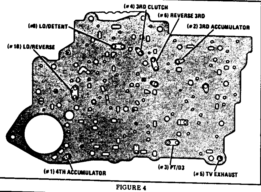
2. Position case gasket marked "C" (refer to Table A on page 4 of this bulletin for correct P/N based on model year application) to spacer plate and place eight (8) check balls (#1 through #6, #9 and #10) on gaskets and spacer plate (refer to Figure #4).
3. Install gaskets, spacer plate, and accumulator plate onto transmission. Temporarily retain the spacer and accumulator plate using small bolt from accumulator housing.
4. Insert the 1-2 accumulator spring in accumulator housing.
5. Install a new teflon seal on the 1-2 accumulator piston (page 200-4R-62, Figure 235, 1983 Service Information Manual).
6. Install 1-2 accumulator piston in 1-2 accumulator housing with dome up; now install 1-2 accumulator assembly. Torque five bolts to 12 N.m (8 ft. lbs.).
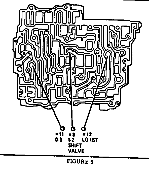
7. Position three (3) check balls (#8,#11 and #12) in control valve assembly (refer to Figure #5).
8. Install control valve assembly to spacer plate gasket marked "VB" (refer to Table A for correct P/N) on top of the control valve assembly.
9. Install control valve assembly to case using the two guide pins as locators. Make sure to align the manual valve with the detent lever. Torque all bolts to 10-14 N.m (7-10 ft. lbs.). It is possible during reassembly to position the manual valve too far into the valve body and still connect the selective lever link to it, which will then prevent the valve body from fitting properly onto the transmission case.
10. Install signal oil pipe and its retaining cup.
11. Install inside manual detent roller and spring assembly, locating tang in control valve and roller on inside detent lever.
12. Install throttle lever and bracket assembly. Refer to page 200-4R-59, step 24,in the 1983 Service Information Manual substeps a through d, for proper installation preocedure.
13. Install TCC solenoid assembly attaching bolts, clips, "O" ring (P/N 8634188) and solenoid.
14. Install all electrical connections.
15. Install transmission oil filter and its "O" ring (P/N 1363951).
16. Install transmission on pan and new gasket (RTV).
TABLE A
1981 200-4R Gasket Kit P/N 8634932 1982 200-4R Gasket Kit P/N 8634976 1983 200-4R Gasket Kit P/N 8634969
General Motors bulletins are intended for use by professional technicians, not a "do-it-yourselfer". They are written to inform those technicians of conditions that may occur on some vehicles, or to provide information that could assist in the proper service of a vehicle. Properly trained technicians have the equipment, tools, safety instructions and know-how to do a job properly and safely. If a condition is described, do not assume that the bulletin applies to your vehicle, or that your vehicle will have that condition. See a General Motors dealer servicing your brand of General Motors vehicle for information on whether your vehicle may benefit from the information.
