FUEL LINE KNOCK/HAMMERING REPLACE FUEL FEED PIPE

MODELS AFFECTED: 1986 CIMMARONS EQUEPPED WITH 2.8L V-6 ENGINE
Some 1986 Cadillac Cimarrons equipped with the 2.8L V-6 engine may exhibit a light knocking or hammering type noise audible in the passenger compartment. The noise may be noticed with the engine cold or warm and is most apparent at idle. This condition may be caused by pressure pulsations in the fuel system generated by fuel injector operation, resulting in hydraulic hammering in chassis fuel pipes. Vehicles exhibiting this condition may be repaired by installation of a new engine fuel feed pipe-expansion chamber assembly, P/N 10100095, following the service procedure in this bulletin.
Parts are expected to be available on October 17, 1988. Until then, normal part orders will not be accepted by GMSPO. Only verifiable emergency VIP orders will be accepted. SPO will make every effort to obtain parts. All parts will be placed on 400 control to waive VIP surcharges. However, the part will be shipped prmium transportation at dealer's expense. All other order types will be cancelled as incorrectly ordered while the 400 control is in place.
Service Procedure:
1. Disconnect negative battery cable and remove fuel tank filler cap.
2. Relieve pressure in fuel system following shop manual procedure.
3. Disconnect electrical connectors to Mass Air Flow (MAF,), Idle Speed Control (ISC), and Throttle Position Sensor (TPS) sensors.
4. Remove air cleaner assembly and duct to throttle body as a unit.
5. Remove cross-over pipe heat shield (two nuts, three screws).
6. Disconnect throule body coolant hoses at coolant pipes.
7. Disconnect EGR transfer tube from EGR valve.
NOTE: CARE MUST BE TAKEN TO ENSURE TRANSFER TUBE IS NOT DISPLACED (BENT) FROM ITS INSTALLED POSITION. SUCH MOVEMENT COULD JEOPARDIZE PART RMGRFFY AND RESLJLT IN EXHAUST GAS LEAKAGE.
8. Disconnect plenum from intake manifold (eight bolts, one stud) and rotate up and rearward.
9. Identify and mark relationship of fuel feed hose to chassis fuel feed pipe. Disconnect fuel feed hose at chassis fuel feed pipe utilizing backup wrench.
NOTICE: FUEL FEED HOSE ASSEMBLIES ARE FORMED PARTS AND MUST BE REINSTALLED IN THE SAME POSITION THEY WERE IN PRIOR TO REMOVAL. TWISTING THE HOSE MAY ADVERSELY AFFECT ENGINE OPERATION AND/OR HOSE INTEGRITY.
10. Disconnect fuel feed pipe at fuel rail.
11. Remove stud retaining fuel feed/rewrn pipe clip to cylinder head.
12. Remove engine fuel feed pipe and fuel feed hose as an assembly.
13. With new fuel feed pipe/expansion chamber, P/N 10100095, positioned next to removed fuel feed pipe and hose, identify and mark hose assembly position on new pipe assembly.
14. Disconnect fuel feed hose from feed pipe and connect to new feed pipe/expansion chamber assembly utilizing backup wrench. Torque fitting to 20-34 N-m ensuring hose is maintained in position identified in previous step.
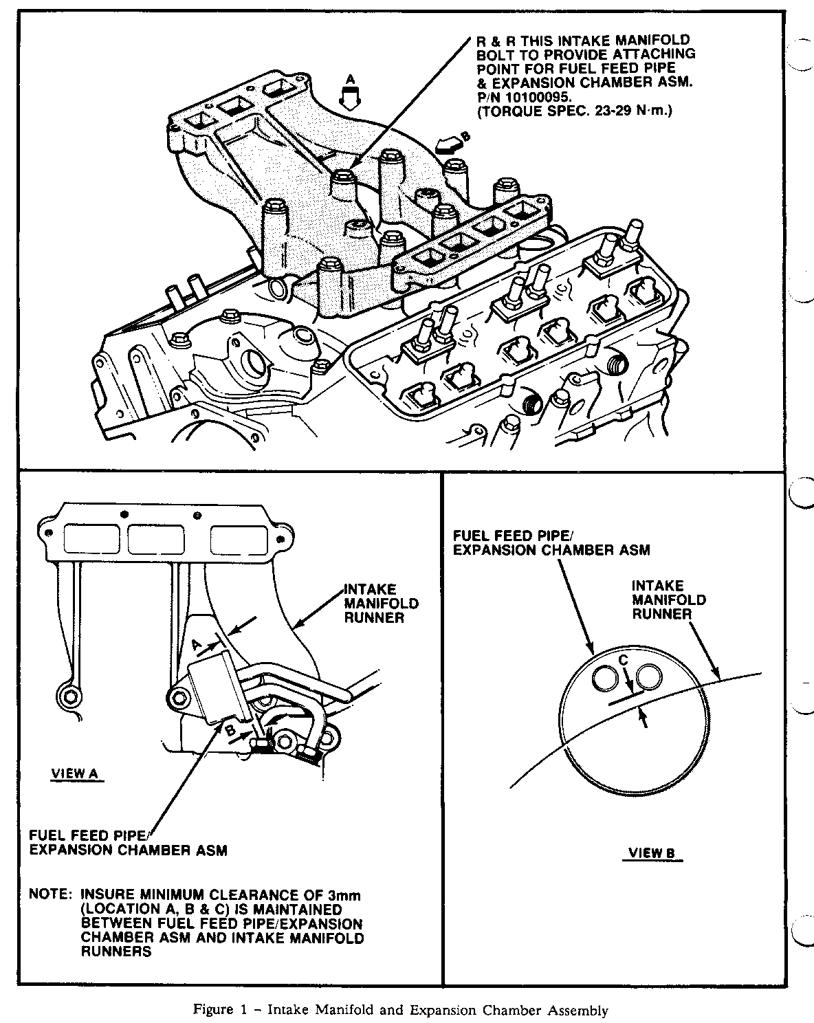
15. Remove intake manifold bolt indicated in Figure 1.
16. Route new fuel feed pipe expansion chamber assembly and hose into position and insert into fuel feed/rewrn pipe clip.
17. Hand start fuel feed pipe fining at fuel rail and feed/return pipe clip stud.
18. Insert intake manifold bolt through expansion chamber bracket and position expansion chamber to ensure clearance between intake manifold runners/expansion chamber, refer to Figure 1, views A and B. Torque intake manifold bolt to 18-24 N-m.
19. Torque fuel feed pipe fitting at fuel rail to 20-35 N-m and retaining clip stud to 37-41 N-m.
20. Reconnect fuel feed hose to chassis fuel feed pipe ensuring position identified in step 9 is maintained and torque to 20-34 N-m utilizing backup wrench on fining.
21. Assemble plenum to intake manifold utilizing new gaskets at both the plenum to intake manifold and EGR valve to EGR transfer tube interface.
22. Torque plenum and EGR transfer tube fasteners to 23-29 N-m.
23. Assemble crossover pipe heat shield to engine.
24. Install air cleaner and duct.
25. Reconnect electrical connectors, battery, and install fuel tank filler cap.
26. Start engine, check all connections for possible fuel or coolant leaks, and correct as required.
Parts required for this installation are noted below and are available from GMSPO:
Quantity Description P/N Required ----------- --- --------
Fuel Feed Pipe/Expansion Chamber 10100095 1 Plenum Gasket Kit 14089058 1 EGR Transfer Tube Gasket 14088263 1
For warranty purposes use Labor Operation T6348 at 1.8 hours.

General Motors bulletins are intended for use by professional technicians, not a "do-it-yourselfer". They are written to inform those technicians of conditions that may occur on some vehicles, or to provide information that could assist in the proper service of a vehicle. Properly trained technicians have the equipment, tools, safety instructions and know-how to do a job properly and safely. If a condition is described, do not assume that the bulletin applies to your vehicle, or that your vehicle will have that condition. See a General Motors dealer servicing your brand of General Motors vehicle for information on whether your vehicle may benefit from the information.
