TORQUE CONVERTER CLUTCH SHUDDER DIAGNOSIS,125C

MODELS AFFECTED: 1982-1986 CIMARRONS WITH THM 125C AUTOMATIC TRANSAXLES
This Bulletin replaces 85-1 which should be destroyed.
It is possible that some conditions described as TCC shudder are actually caused by engine, engine control or other devices rather than transmission components. Operations described in Serviceman Bulletin 85-1, Group 7, No. 110, were at times being performed before the condition was verified as a transmission/torque converter related condition.
When the Torque Converter Clutch is applied, all slip in the converter is eliminated. Consequently, all input from the engine to the powertrain beginning with the engine firing impulses can be transmitted in an erratic or uneven power input to the drive axles. This can produce a shudder condition. The condition may be noticeable as the TCC applies and/or after apply during an engine torque load. It may also be constant or vary in severity depending on conditions of operation.
ENGINE RELATED DIAGNOSIS
Before proceeding to the TCC diagnostic and repair section of this bulletin, the following should first be inspected and eliminated as possible causes. Failure to eliminate these possible causes may result in a transmission repair that is unwarranted and will result in no improvement.
1. Verify that the fuel system is controlling and correct any current trouble codes. Perform the System Performance Check (1982 Cimarron Manual Section 6E) or Diagnostic Circuit Check (1983-1986 Cimarron Manual Section 6E2.)
2. Check HEI system, especially secondary wiring and spark plugs. Intermittent spark plug wires and/or cracked or fouled spark plugs can cause surge or chuggle. For diagnosis of cracked plugs/shorted wires, see Serviceman 83-25, Section 6D.
3. Check for proper ignition timing per the engine tune-up label. Timing that is retarded below specification may cause surge or chuggle. See Serviceman Bulletin 84-50, Group 6C, to correct spark knock/detonation in 1983 Cimarrons with Federal Emission systems.
4. Check the EST system for proper operation. Check for the presence of code 42. On 1983 and 1984 cars that have had the Special Policy Adjustment for cold startability (84-P-1), check for proper operation of the cold start relay. A 1983 or 1984 Cimarron with the cold startability kit applied WILL NOT SET A CODE 42 when an ignition system fault exists.
5. Check for proper EGR system operation. See Cimarron Service Information Manual Section 6E for 1982 Cimarrons; see Section 6E2 for 1983 through 1986 models. Excessive EGR flow due to improper EGR operation or restricted exhaust may cause surge or chuggle.
6. Check the canister purge system for proper operation and for the charcoal canister loaded with fuel. See Cimarron Service Information Manual Section 6E for 1982 Cimarrons; see Section 6E2 for 1983 through 1986 models.
7. In 1983 Cimarrons, check for chuggle with cruise control applied, especially at low speeds or on downhill grades. If present, see Serviceman 86-19, Group 9.
8. Check for intermittent MAT or coolant sensor connectors. See Serviceman 85-108, Group 6C.
9. Check for vehicle speed sensor faults. See page 2, of this bulletin.
10. Check engine grounds for proper connection, tightness and star washers installed. See Section 8A of Service Information Manual for location of G100, G101 and G111 (all models), G109 and G200 (1982 only), and G112 and G113 (1983 through 1986 models).
11. Intermittent or flashing "Check Engine" light, which may indicate an ECM reset condition. See Serviceman Bulletin 84-92, Group 6C, to diagnose.
This list of items is not all inclusive of problem areas that could affect engine impulse variations transmitted to the drive axles.
TRANSMISSION RELATED DIAGNOSIS
Some THM 125C transmissions may exhibit Torque Converter Clutch (TCC) shudder as the TCC applies and/or after it applies when the accelerator pedal is depressed slowly (Engine Torque Load Shudder). These types of shudders are best described as a jerking sensation. In some cases the shudder may be severe enough to cause the instrument panel to vibrate.
CONDITION CAUSE AND CORRECTION --------- -------------------- TCC APPLY TCC CROWD SHUDDER SHUDDER --------- --------- X 1. Apply shudder can be caused by dimpling of the converter cover. This will occur when the bolt bottoms out in the boss before it is torqued. The bolt end will put a dimple in the converter cover in the area that the friction material on the T.C.C. plate contacts the cover, causing uneven apply. The cause may be a too long bolt or shallow hole in the threaded area of the converter attaching boss. This eventually results in T.C.C. slip.
X X 2. Shudder may also be evidenced as the result of a T.C.C. solenoid or solenoid seal leaking. This will result in delayed T.C.C. apply slip and/or shudder due to T.C.C. apply pressure loss or drop.
X X 3. An intermittent incorrect signal from the Vehicle Speed Sensor (VSS). Dirt or grease on the reflective bar in the VSS may be sending an incorrect or erratic signal so that the converter clutch engages at too low a speed. Remove the speedometer cluster and VSS and remove any dirt or grease (refer to Serviceman Bulletin 83-102, Group 7, Number 74, Item D).
X X 4. The auxiliary valve body cover attaching bolts may be loose or the bolt threads/holes may be shallow. If the holes are shallow, the bolts will bottom out before the cover is tight (refer to Serviceman Bulletin 83-62, Group 7, Number 64).
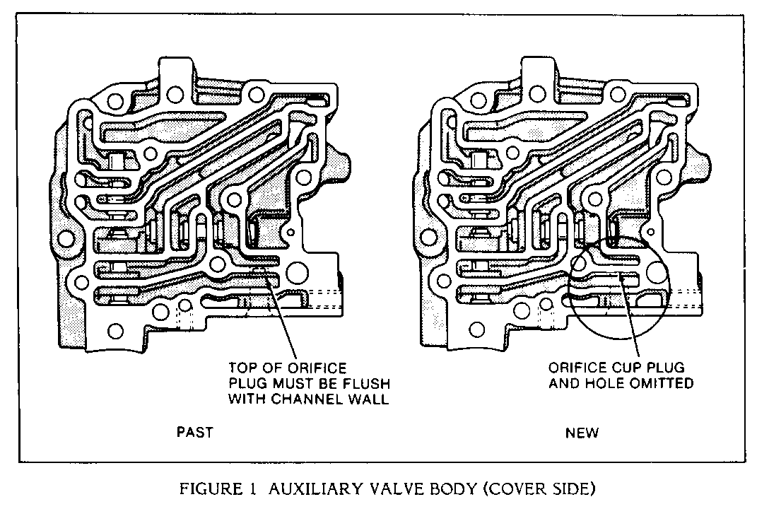
X 5. Some 1982 models were built with either an exhaust hole or an orifice cup plug in the auxiliary valve body cover. The auxiliary valve body cover was changed to a solid cover (no exhaust hole or orifice cup plug in 1982. The service auxiliary valve body cover, part number 8643645, should be used on all models to prevent shudder. The service part does not have an orifice cup plug (refer to Serviceman Bulletin 83-102, Group 7, Number 74, Item E).
X 6. There are two types of auxiliary valve bodies in service. One has an orifice cup plug and the other does not (Figure 1). If the transmission being serviced has the auxiliary valve body with the orifice cup plug, particles of the auxiliary valve body cover gasket may have torn loose. This material may be causing the Torque Converter Clutch apply valve to bind and/or plug the converter release orifice in the control valve body spacer plate. If this is found, disassemble the auxiliary valve body and thoroughly clean. Also, be sure to remove any gasket particles in the valve body spacer plate converter release orifice hole and replace the auxiliary valve body cover gasket, P/N 8653947 (refer to Serviceman Bulletin 84-70, Group 7, Number 101).
X 7. Check the valves in the auxiliary valve body for free movement. They must move in the bore without sticking. (Refer to Serviceman Bulletin 83-102, Group 7, Number 74, Item F.)
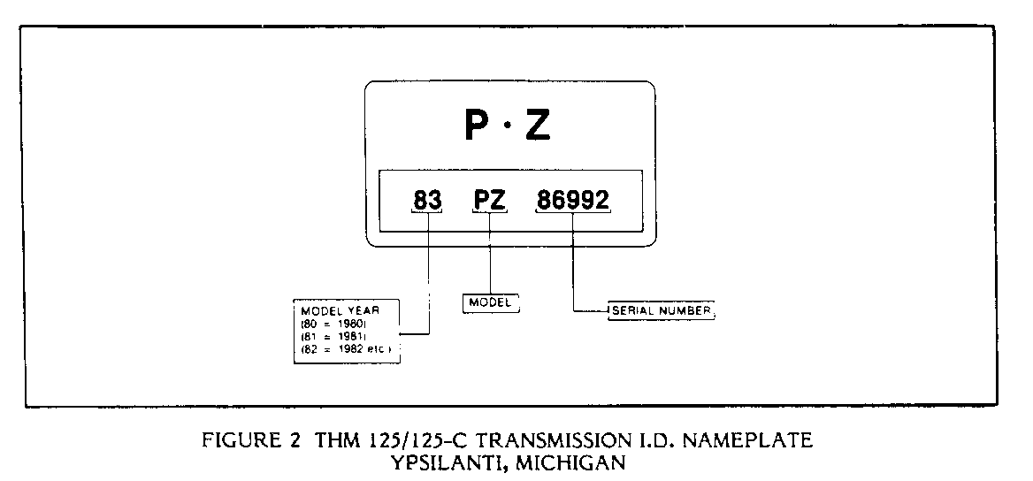
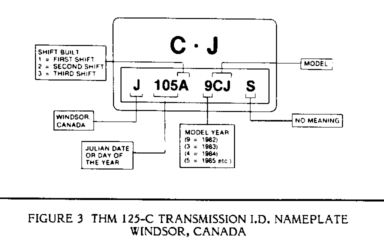
X 8. The auxiliary valve body converter clutch control regulator spring may be weak and require replacement with the new increased load spring. Beginning with 1984 model year transaxle serial numbers CA 2226 and CB 156657, the new spring (P/N 8637888) went into production. To correct apply shudder on any 1982 or 1983 as well as before number 1984 model year transaxles, install the increased load auxiliary valve body converter clutch control regulator spring (P/N 8637888). For explanations of transaxle nameplates, refer to Figure 2 (U.S. built) and Figure 3 (Canadian built).
X X 9. Inspect the pump shaft to valve body seal for cuts, damage, or distortion (refer to Serviceman Bulletins 83- 102, Group 7, Number 74, Item C, and 82-93, Group 7, Number 45).
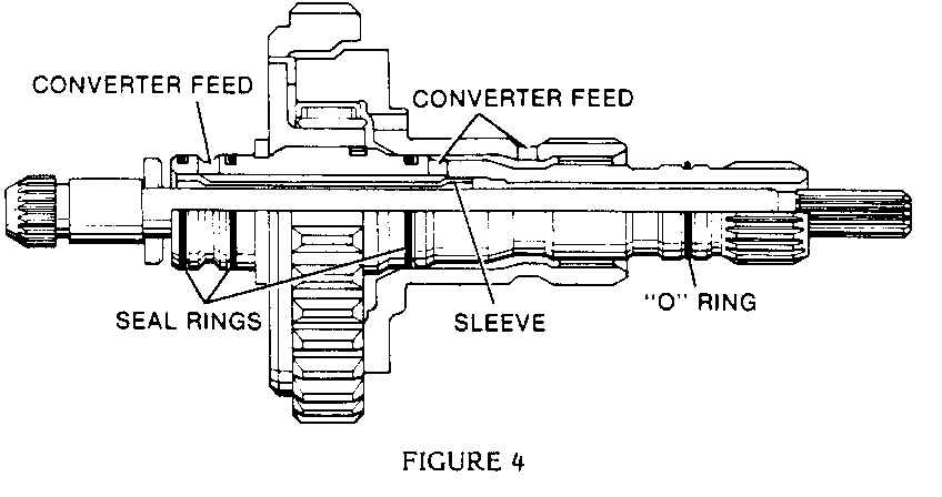
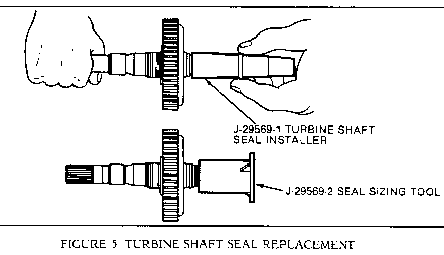
X 10. Inspect the turbine shaft Teflon seals and "O" ring seal for damage, cuts, or distortion (see Figure 4). If the Teflon seals require replacement, make sure they are installed and sized as shown in Figure 5 (refer to serviceman Bulletin 83-102, Group 7, Number 74, Item A).
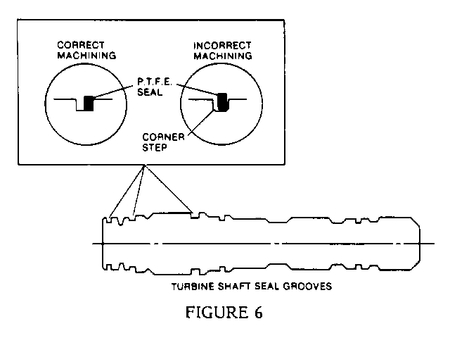
X 11. Inspect the turbine shaft seal grooves. A step in the bottom corners of the seal groove will keep the seal from contacting the side wall of the groove and will prevent proper sealing (Figure 6). If this condition is found, replace the turbine shaft and seals (refer to Serviceman Bulletin 83-102, Group 7, Number 74, Item B).
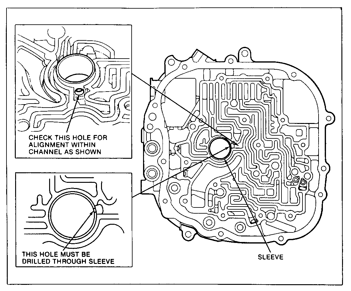
X 12. Check the case cover sleeve converter feed oil hole that it is aligned with the oil channel in the case cover (Figure 7).
X 13. Check the converter end play, using tool J-29830A. The end play specification is .5mm (.020"). Converters with end play more than .5mm (.020") must be replaced.
X 14. The turbine shaft sleeve may have excessive internal leakage. If all of the above items are OK, replace the turbine shaft.
General Motors bulletins are intended for use by professional technicians, not a "do-it-yourselfer". They are written to inform those technicians of conditions that may occur on some vehicles, or to provide information that could assist in the proper service of a vehicle. Properly trained technicians have the equipment, tools, safety instructions and know-how to do a job properly and safely. If a condition is described, do not assume that the bulletin applies to your vehicle, or that your vehicle will have that condition. See a General Motors dealer servicing your brand of General Motors vehicle for information on whether your vehicle may benefit from the information.
