Tools Required
J 44212 Camshaft Holding Tool
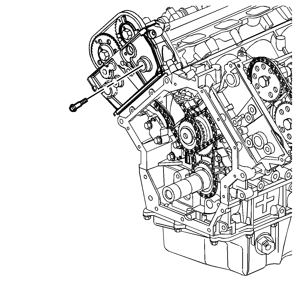
- Install the right secondary camshaft drive chain guide.
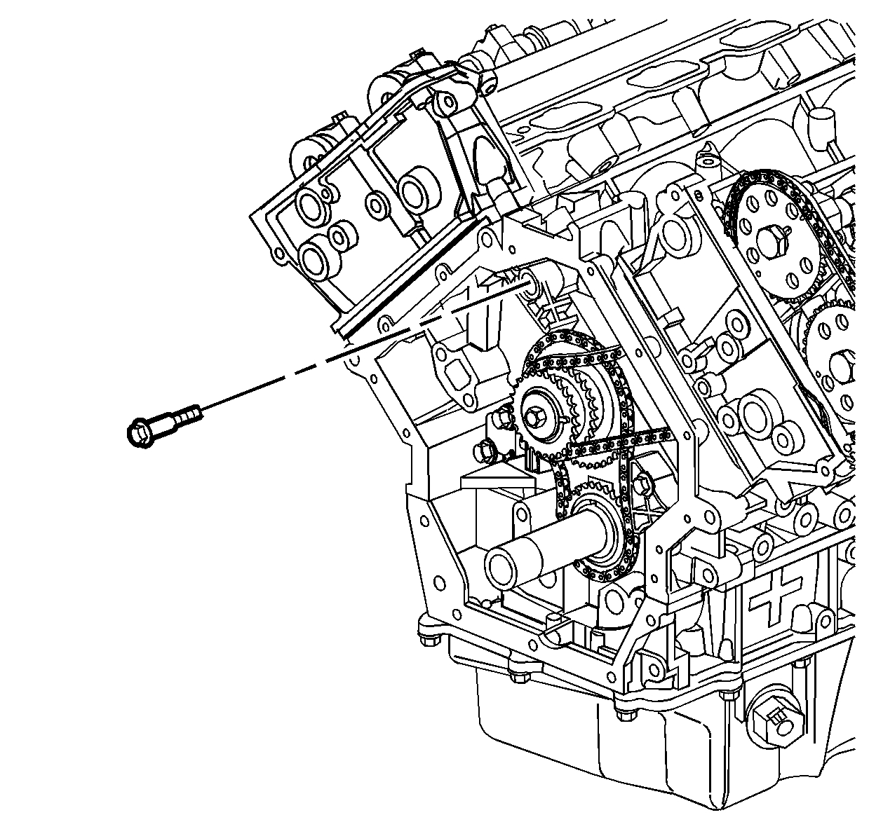
- Loosely install the lower right secondary camshaft drive chain guide bolt.
- Install the right secondary camshaft drive chain shoe.
- Install the right secondary camshaft drive chain shoe bolt.
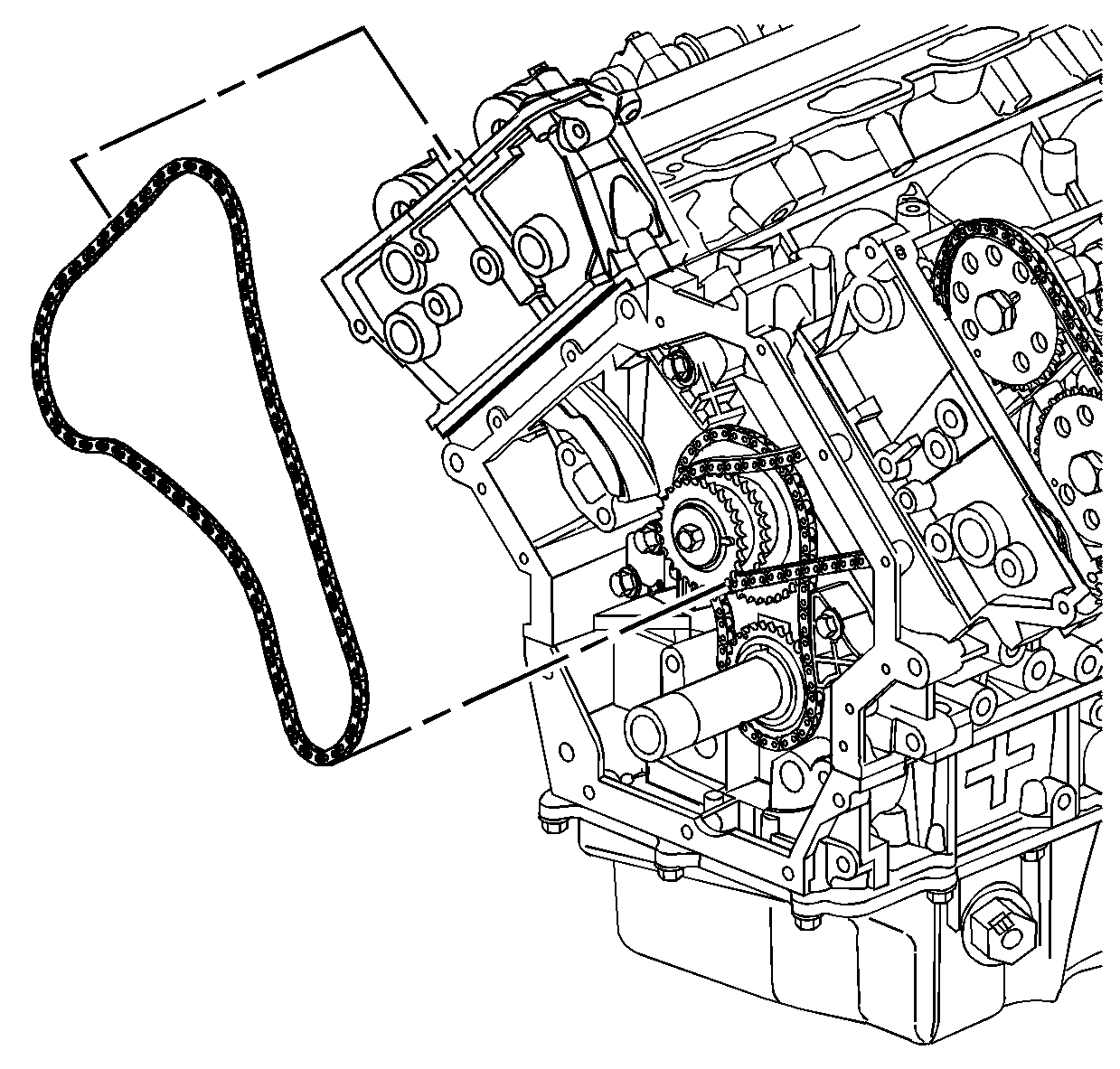
- Install the right secondary camshaft drive chain by sliding the chain down through the right cylinder head and placing the chain on the end of the camshafts.
- Route the right secondary camshaft drive chain around the outer row of the intermediate drive chain sprocket teeth.
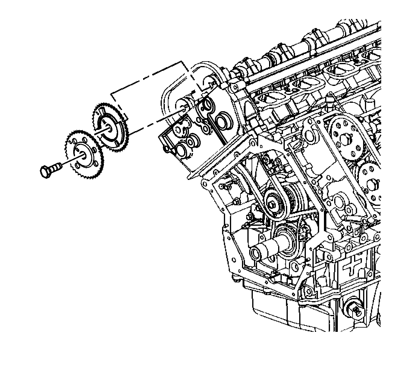
- Install the right intake and exhaust camshaft sprockets into the right secondary camshaft drive chain.
- Install the right intake and exhaust camshafts sprockets onto the camshafts. The camshaft sprocket slot marked "RI" which indicates right intake, engages the intake camshaft pin and the camshaft sprocket slot marked "RE" which indicates right exhaust, engages the exhaust camshaft pin.
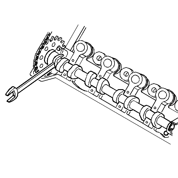
- If necessary, use an open wrench on the hex cast near the front of each camshaft to help align the sprocket slot to the camshaft pin.
- Loosely install the right intake and exhaust camshaft sprocket bolts.
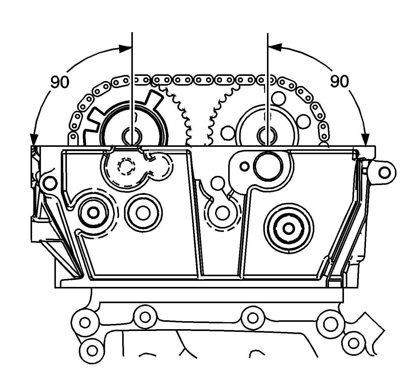
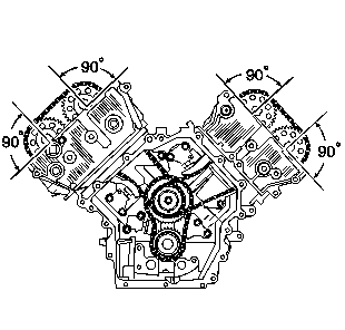
- Ensure the perpendicular alignment of the right intake and exhaust camshaft sprocket slots and camshaft pins to the cylinder head.
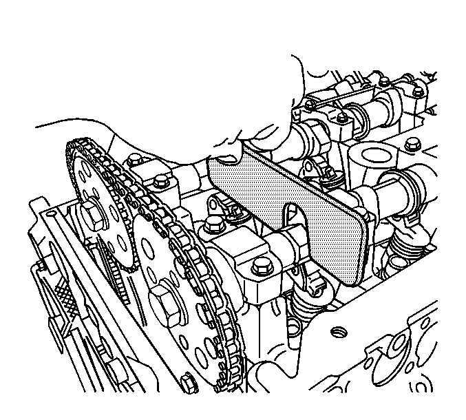
- Install the J 44212 to the right cylinder head camshafts.
- Install the upper right secondary camshaft drive chain guide bolt.
- Collapse the right secondary camshaft drive chain tensioner using the following procedure:
- When the ratchet lever moves to the first detent a click should be heard and felt. Insert a pin through the hole in the release lever in order to lock the right secondary camshaft drive chain tensioner shoe in the collapsed position.
- Install the right secondary camshaft drive chain tensioner.
- Install the right secondary camshaft drive chain tensioner bolts.
- Remove pin from right secondary camshaft drive chain tensioner lever.
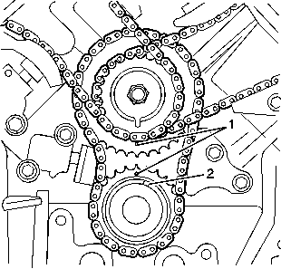
- Ensure the correct alignment of all secondary timing components.
- Ensure the correct alignment of all primary timing components (1, 2).
- Tighten ALL camshaft sprocket bolts. Use the hex cast into each camshaft to prevent engine rotation and provide leverage.
- Install the cylinder head core hole plugs located in the cylinder heads. Ensure the O-ring seal is on each cylinder head core hole plug.
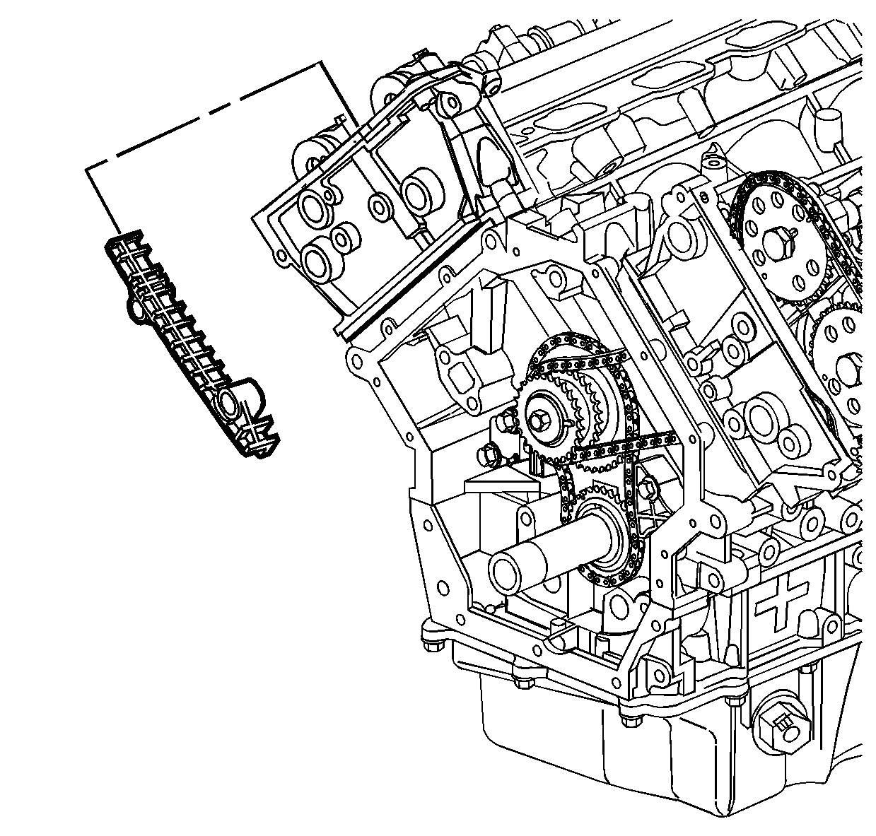
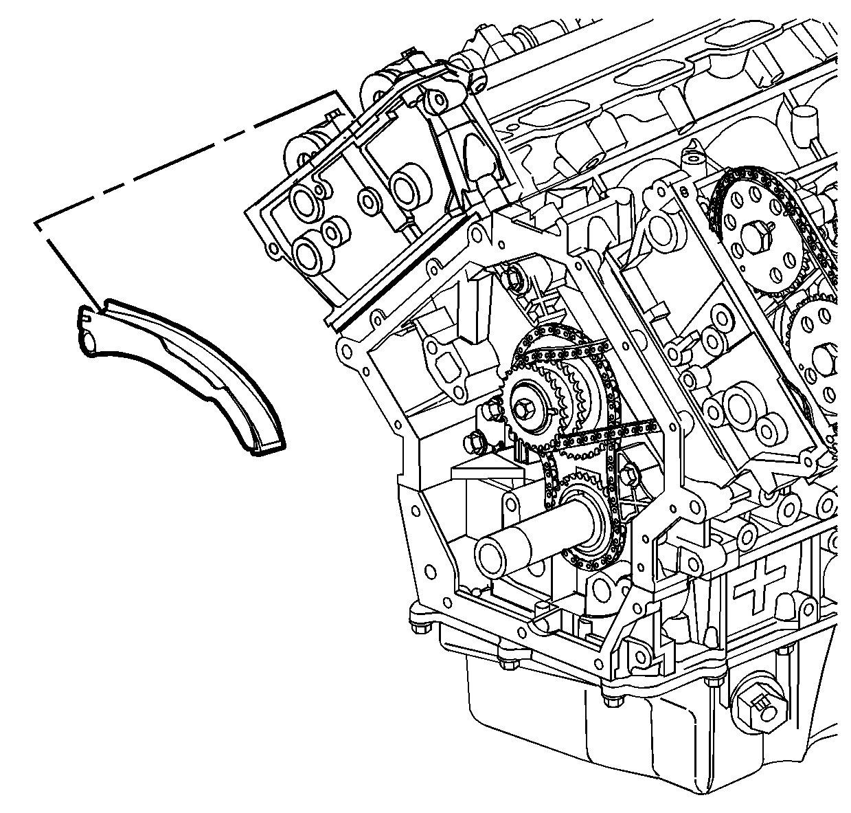
Notice: Refer to Fastener Notice in the Preface section.
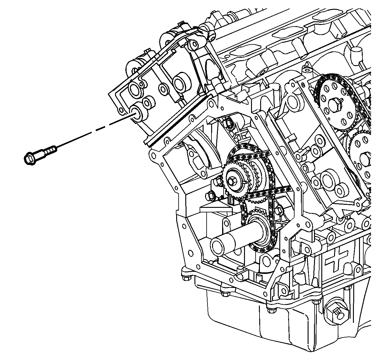
Tighten
Tighten the right secondary camshaft drive chain shoe bolt to 25 N·m (18 lb ft).
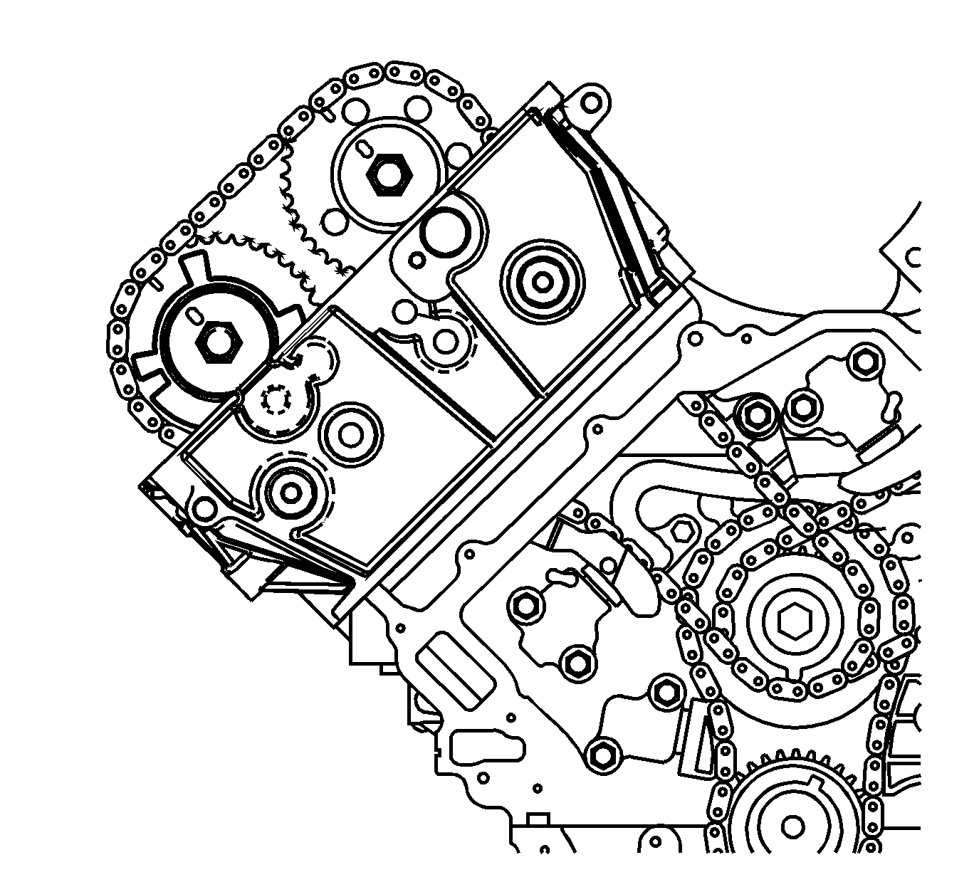
Important: Do not use the stamped indicator marks for perpendicular alignment when installing the timing chain.
Tighten
Tighten BOTH the upper and lower right secondary camshaft drive chain guide bolts to 25 N·m (18 lb ft).
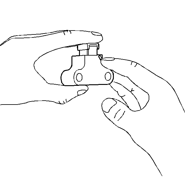
| 14.1. | Rotate the ratchet release lever counter-clockwise and hold. |
| 14.2. | Collapse the right secondary camshaft drive chain tensioner shoe and hold. |
| 14.3. | Release the ratchet lever and slowly release the pressure on the shoe. |
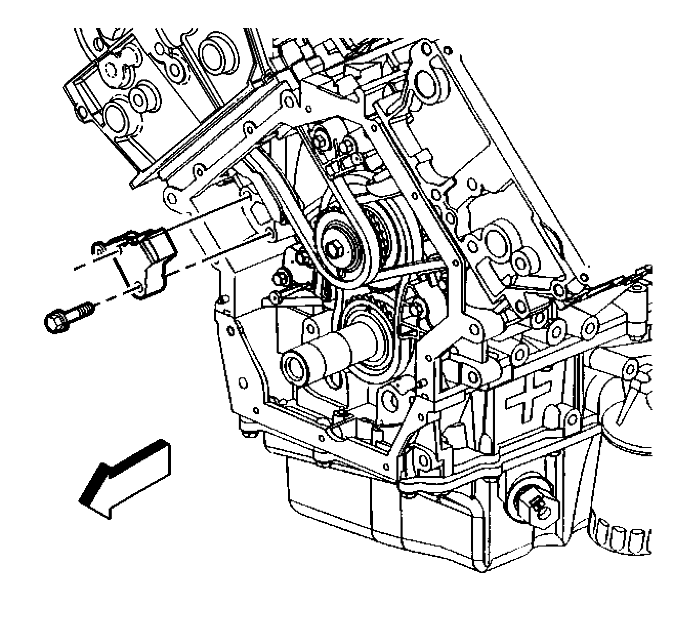
Important: Ensure the right secondary camshaft drive chain tensioner release lever is facing out.
Tighten
Tighten the right secondary camshaft drive chain tensioner bolts to 25 N·m (18 lb ft).
Notice: Refer to Torque Reaction Against Timing Drive Chain Notice in the Preface section.

Tighten
Tighten ALL camshaft sprocket bolts to 120 N·m (90 lb ft).
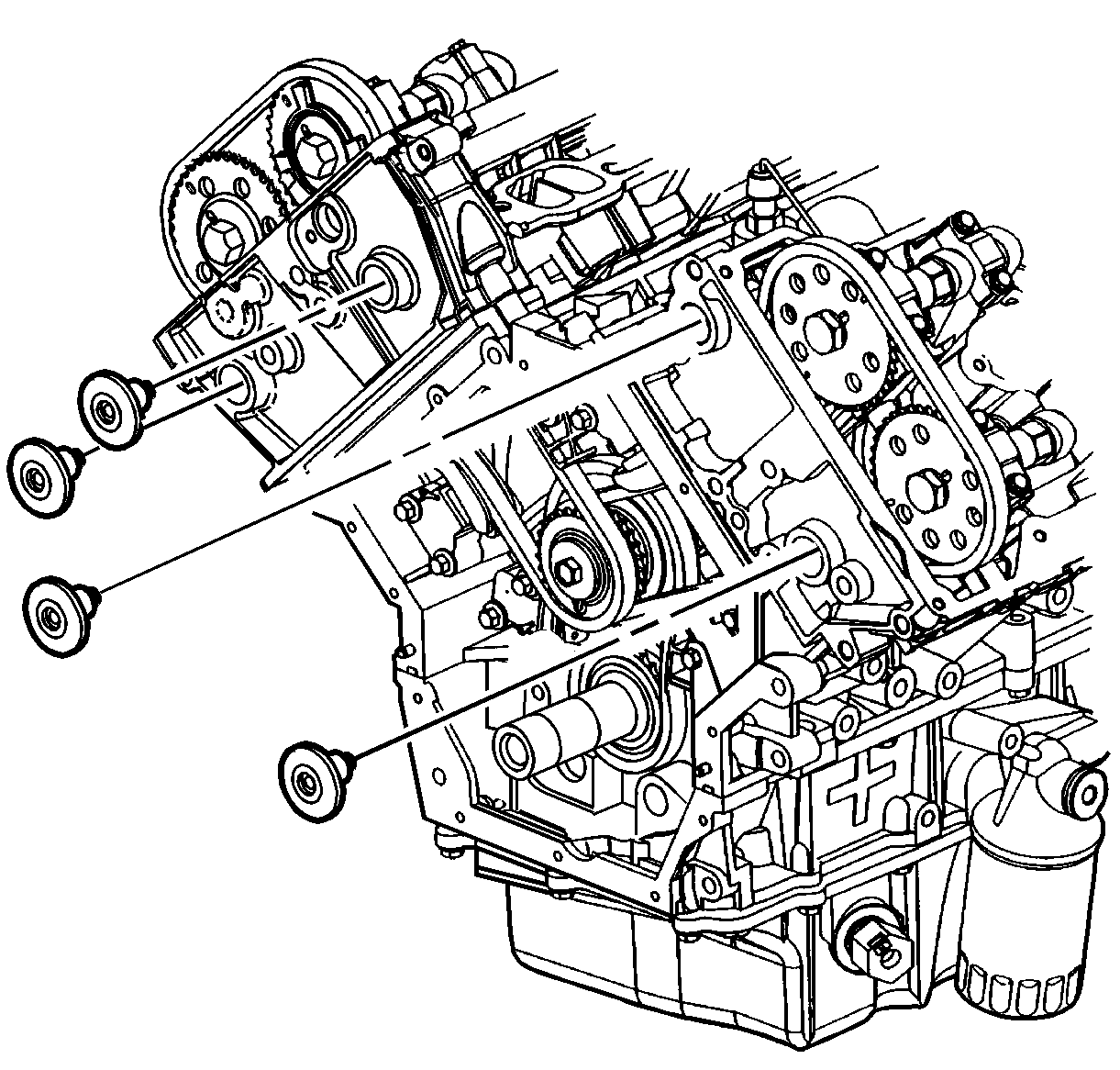
Tighten
Tighten the cylinder head core hole plugs to 4.5 N·m (39 lb in).
