GM Service Manual Online
For 1990-2009 cars only

Steering Knuckle Replacement FE7

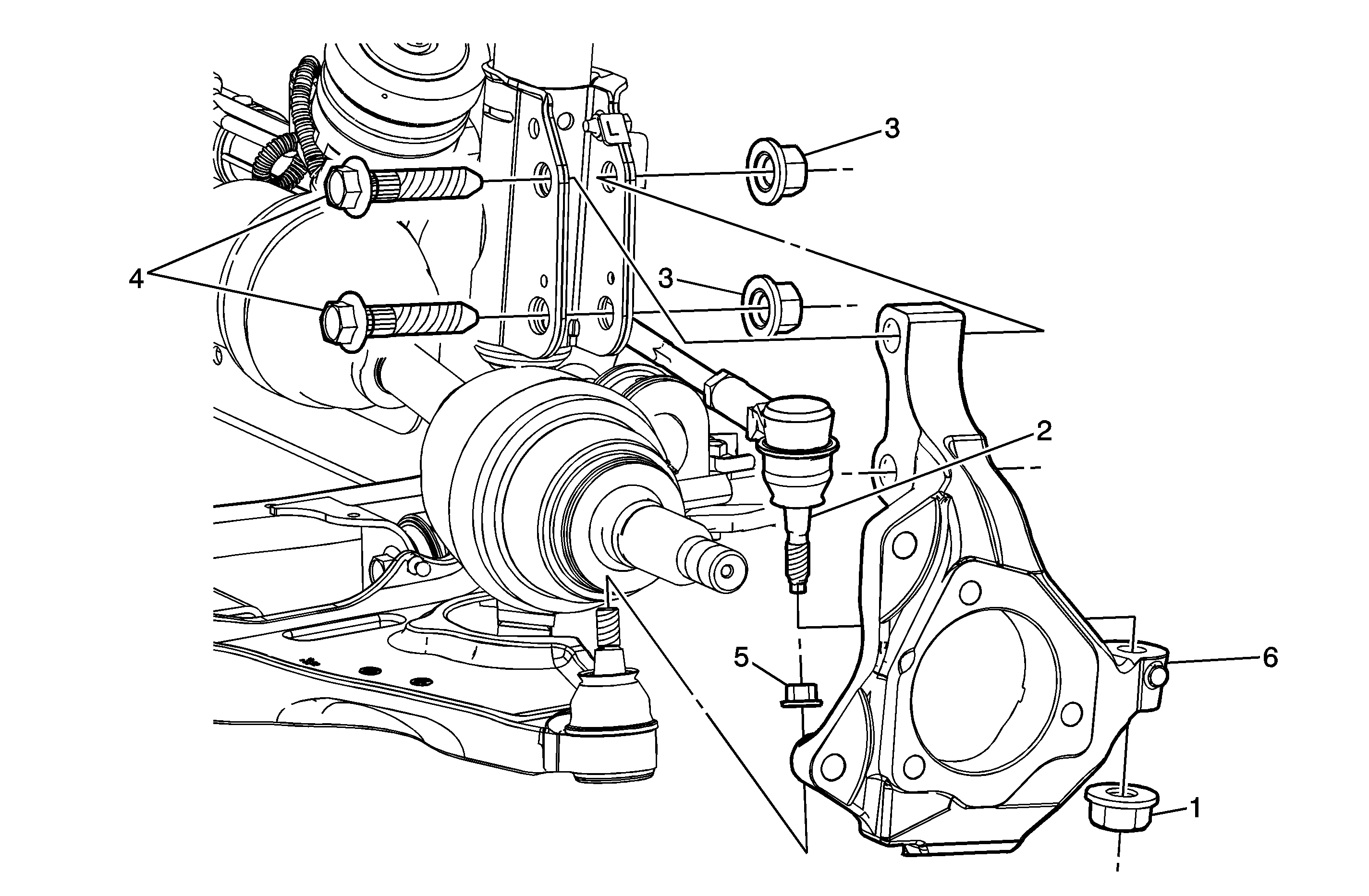
Object Number: 1659425  Size: MF

Callout

Component Name

Tools Required

    • J 24319-B Steering Linkage and Tie Rod Puller
    • J 39549 Ball Joint and Tie Rod End Separator

Preliminary Procedures

  1. Raise and support the vehicle. Refer to Lifting and Jacking the Vehicle.
  2. Remove the front tire and wheel assembly. Refer to Tire and Wheel Removal and Installation.
  3. Remove the brake rotor from the wheel hub/bearing. Refer to Front Brake Rotor Replacement.
  4. Remove the wheel bearing/hub. Refer to Front Wheel Bearing and Hub Replacement.

1

Lower Ball Joint Nut

Notice: Refer to Fastener Notice in the Preface section.

Tip

    • Use the J 39549 to separate the lower ball joint from the control arm.
    • Always replace the ball joint nut after it has been used.

Tighten
30 N·m (22 lb ft) plus an additional 210 degrees

2

Outer Tie Rod End Nut

Tip

    • Use the J 24319-B to separate the tie rod end from the steering knuckle.
    • Always replace the tie rod end nut after it has been used.

Tighten
30 N·m (22 lb ft) plus an additional 200 degrees

3

Strut to Steering Knuckle Nut (Qty: 2)

Tighten
177 N·m (131 lb ft)

4

Strut to Steering Knuckle Bolt (Qty: 2)

5

Steering Knuckle

Procedure

Perform a wheel alignment. Refer to Wheel Alignment Specifications

Steering Knuckle Replacement FE1, FE3


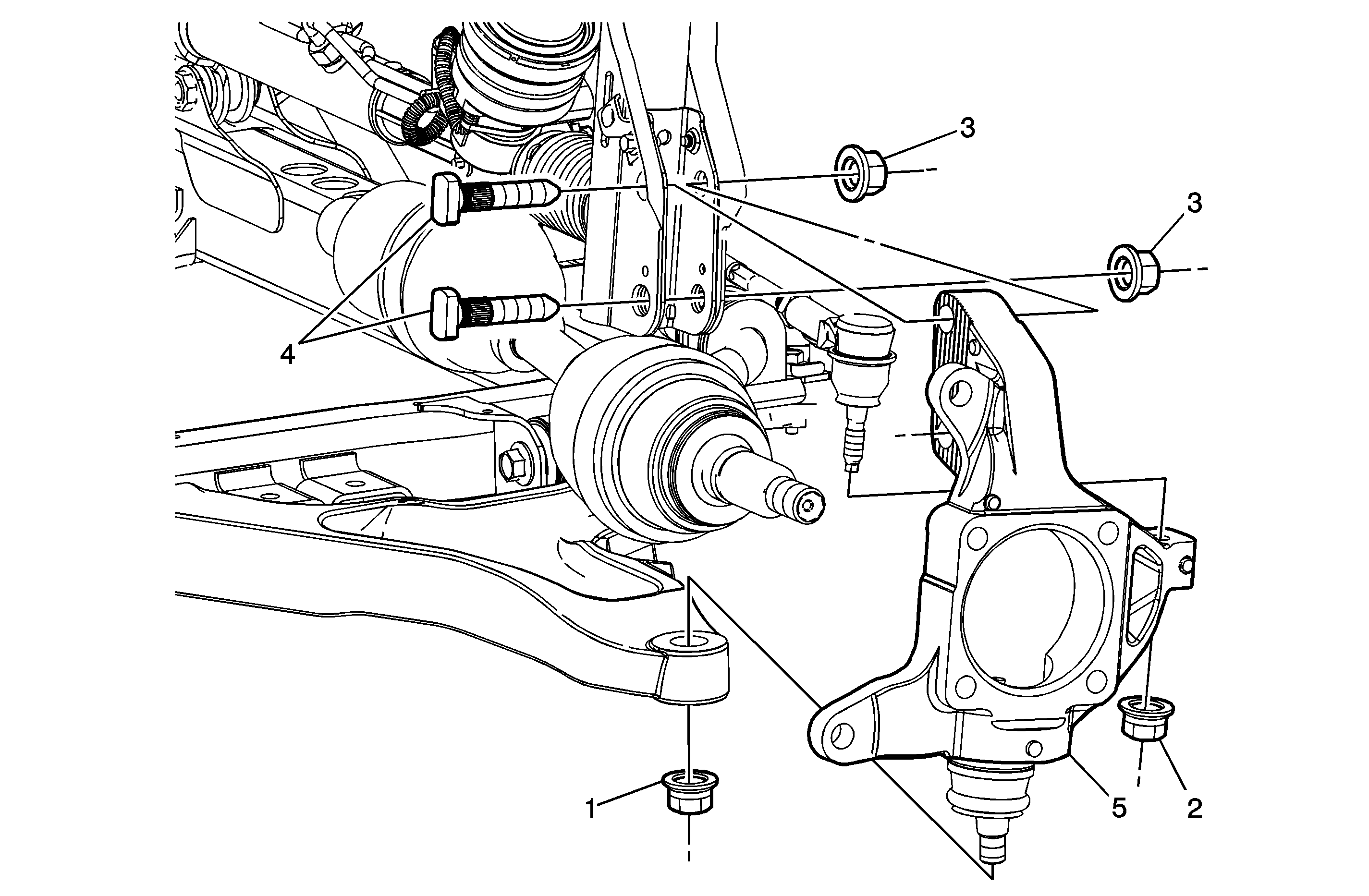
Object Number: 1659441  Size: MF

Callout

Component Name

Notice: Refer to Fastener Notice in the Preface section.

Fastener Tightening Specifications: Refer to Fastener Tightening Specifications.

Notice: The ball stud must not rotate during disassembly or reassembly. Hand tools must be used to keep the ball stud from rotating. If air tools are used and the stud is allowed to rotate, damage to the ball stud and/or stud mounting hole may occur.

Tools Required

    • J 24319-B Steering Linkage and Tie Rod Puller
    • J 43828 Ball Joint and Tie Rod End Separator

Preliminary Procedures

  1. Raise and support the vehicle. Refer to Lifting and Jacking the Vehicle.
  2. Remove the front tire and wheel assembly. Refer to Tire and Wheel Removal and Installation.
  3. Remove the brake rotor from the wheel hub/bearing. Refer to Front Brake Rotor Replacement.
  4. Remove the wheel bearing/hub. Refer to Front Wheel Bearing and Hub Replacement.

1

Outer Tie Rod End Nut

Tip

    • Use the J 24319-B to separate the tie rod end from the steering knuckle.
    • Always replace the tie rod end nut after it has been used.

Tighten
30 N·m (22 lb ft) plus an additional 200 degrees

2

Outer Tie Rod End

3

Strut to Steering Knuckle Nut (Qty: 2)

Tighten
147 N·m (108 lb ft)

4

Strut to Steering Knuckle Bolt (Qty: 2)

5

Lower Ball Joint Nut

Tip

    • Use the J 43828 to separate the ball joint from the lower control arm.
    • Always replace the ball joint nut after it has been used.

Tighten
30 N·m (22 lb ft) plus an additional 210 degrees

6

Steering Knuckle

Tip
Perfom a wheel alignment. Refer to Wheel Alignment Specifications