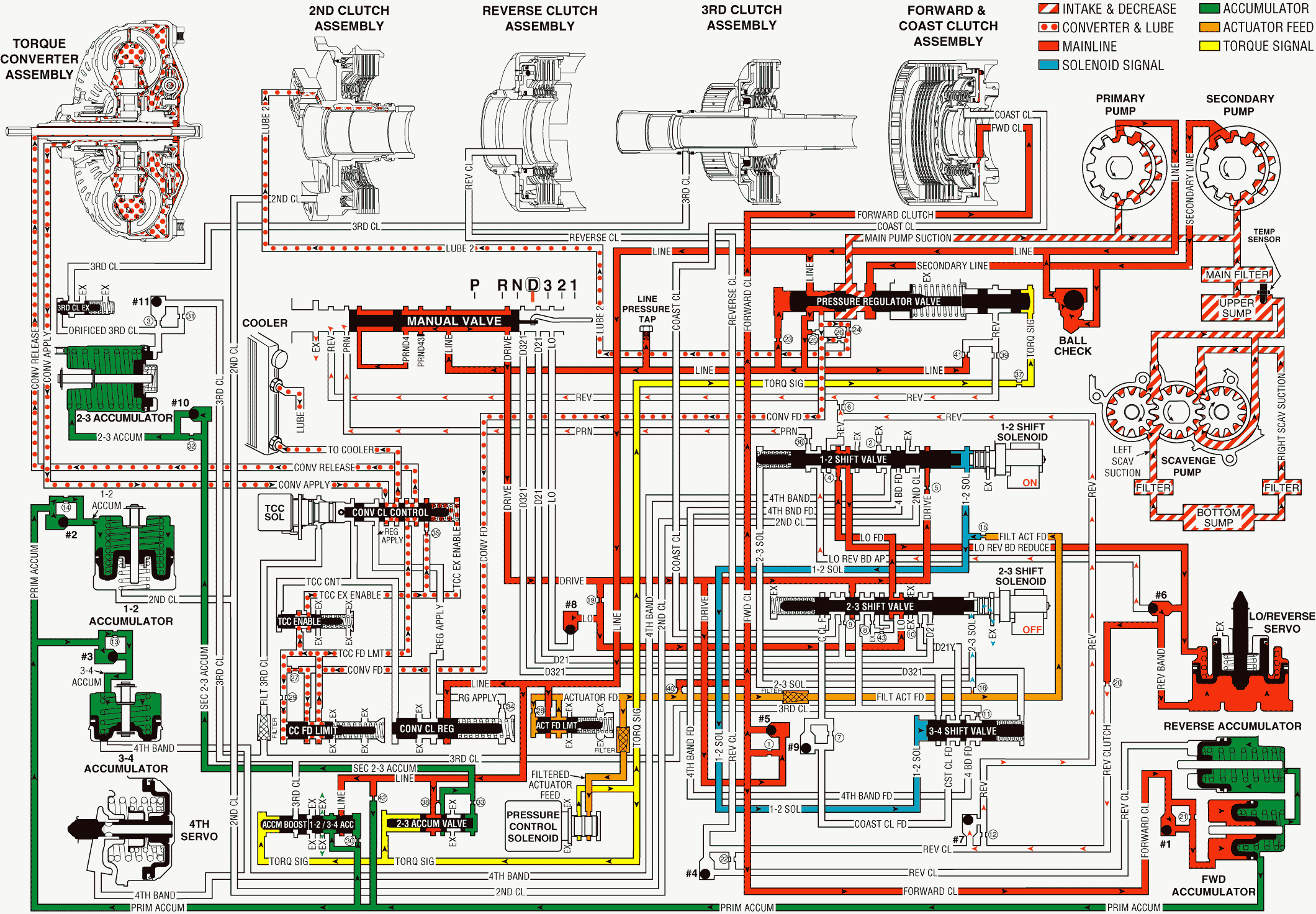
When the gear selector lever is moved to Overdrive Range D, the manual valve moves and allows line pressure to fill the drive fluid circuit. Changes to the hydraulic and the electrical systems in the transmission are as follows:
Forward Clutch Applies
Manual Valve
Mechanically controlled through the gear selector lever, the manual valve directs line pressure into the PRND43, the PRND4, and the drive circuits. Drive fluid pressure is then routed to checkball #5, to the forward orifice bypass valve, to the 1-2 shift valve, to the 2-3 shift valve, and through orifice #19.
Internal Mode Switch (IMS)
The internal mode switch (IMS) is a sliding contact electrical switch assembly that corresponds to the PRNDL position selected. Each of the PRNDL positions has a unique ground pattern on the five wires from the TCM. The IMS consists of two major components: The housing, which houses the tracks and makes up the stationary contacts. The Insulator assembly makes up the moving contacts and is linked to the detent lever. The range detection is accomplished by securing the moving contacts of the IMS to the detent lever. When the driver selects a PRNDL position, the detent lever inside the transaxle rotates. This slides the IMS moving contacts which in return grounds the five wires in a unique pattern for each gear selection corresponding to the PRNDL position selected. The IMS is electrically connected by six wires (four of which the TCM supplies voltage to and one wire that is a common ground and one wire is connected directly to the ECM) to the transaxle pass through connector.
1-2 Shift Solenoid (SS) Valve
Energized by the PCM (turned ON), high pressure in the fluid circuit of the 1-2 SS valve holds the 1-2 shift valve in the downshifted position. The same pressure holds the 3-4 shift valve in the upshifted position.
1-2 Shift Valve
Held in the downshifted position, the 1-2 shift valve allows orificed Low feed fluid to pass through the valve and enter the Low & Reverse band reduce passage. Low & Reverse band reduce fluid is then routed to checkball #6. The fluid is also routed to the spring side of the Low & Reverse servo piston.
2-3 Shift Solenoid (SS) Valve
De-energized by the PCM (turned OFF), the 2-3 SS valve allows high pressure to exhaust through the solenoid while maintaining low pressure in the circuit at the 1-2 shift valve.
#5 Checkball (Drive and Forward Clutch)
Located in the valve body, drive fluid seats the #6 checkball against the spacer plate thereby routing drive fluid through orifice #1 into the forward clutch circuit. Forward clutch fluid is then routed to checkball #1 and to the forward clutch piston to apply the forward clutch.
#1 Checkball (Forward Clutch)
Located in the accumulator housing, the #1 checkball is unseated by forward clutch pressure. This allows forward clutch fluid to actuate the forward accumulator piston.
Forward Accumulator
Forward clutch fluid actuates the forward accumulator piston during the apply of the forward clutch. Primary accumulator fluid on the spring side of the piston is forced back through its circuit to the 1-2 & 3-4 accumulator valve.
1-2 & 3-4 Accumulator Valve
Biased by torque signal and by orificed primary accumulator fluid pressures, this valve regulates the exhaust of primary accumulator fluid during the apply of the forward clutch.
2-3 Shift Valve
A spring force holds the 2-3 shift valve in the downshifted position. This valve allows Low feed fluid to pass through the valve and enter the Low fluid passage. Low fluid is then routed to checkball #8, where the fluid seats the checkball in order to prevent fluid from exhausting at the manual valve.
Low & Reverse Band Applied
Low & Reverse Servo
Low & Reverse band reduce fluid from the 1-2 shift valve seats checkball #6 against the Low & Reverse band apply passage. Fluid is then routed to the spring side of the Low & Reverse servo piston, and into the reverse clutch circuit. In this gear range the Low & Reverse band remains applied, despite the spring force and the Low & Reverse band pressure acting on the Low & Reverse servo piston.
#6 Checkball (Low & Reverse Band Apply, Reduce)
The #6 checkball is held against the Low & Reverse band apply circuit. The checkball routes fluid to the reverse clutch circuit. Reverse clutch fluid is then routed to the manual valve where the fluid exhausts.
1-2 Shift Valve
Operating in the downshifted position, Low & Reverse band apply fluid passes through the valve and enters the orificed PRN circuit. Orificed PRN fluid is the routed to the manual valve where the fluid exhausts.
Overdrive Range, First Gear

