For 1990-2009 cars only
Stabilizer Shaft Replacement FE7
Special Tools
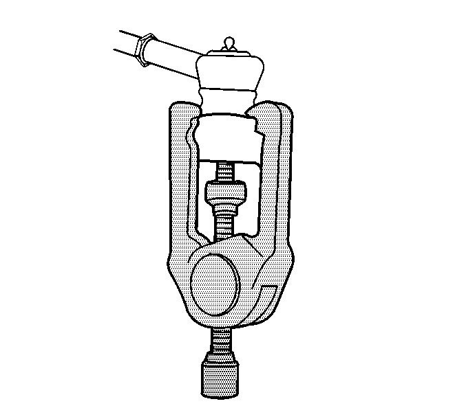
J 24319-B Universal Steering Linkage Puller
Removal Procedure
- Raise and support the vehicle. Refer to Lifting and Jacking the Vehicle.
- Remove the tire and wheels. Refer to Tire and Wheel Removal and Installation.
- Remove the stabilizer links. Refer to Stabilizer Shaft Link Replacement.
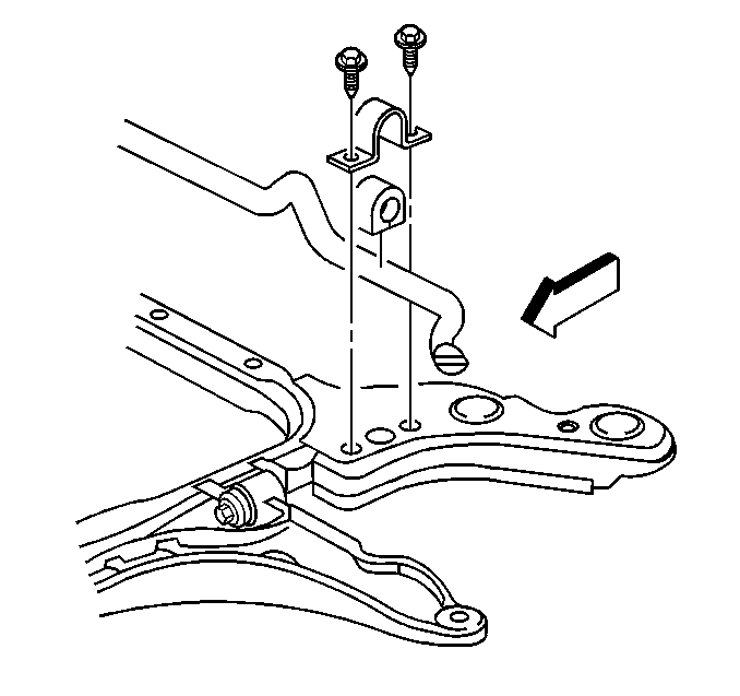
- Remove the stabilizer shaft bracket bolts.
- Remove the stabilizer shaft brackets.
- Remove the outer tie rod retaining nuts.
- Using J 24319-B , disconnect the outer tie rod from the steering knuckle.
- Separate the ball joint. Refer to Lower Control Arm Ball Joint Replacement.
- Turn the right steering knuckle to the left, and guide the stabilizer shaft half out the right side of the vehicle in an upward direction, then remove the stabilizer shaft out the bottom center of the vehicle.
Installation Procedure
- Install the stabilizer shaft to the vehicle.
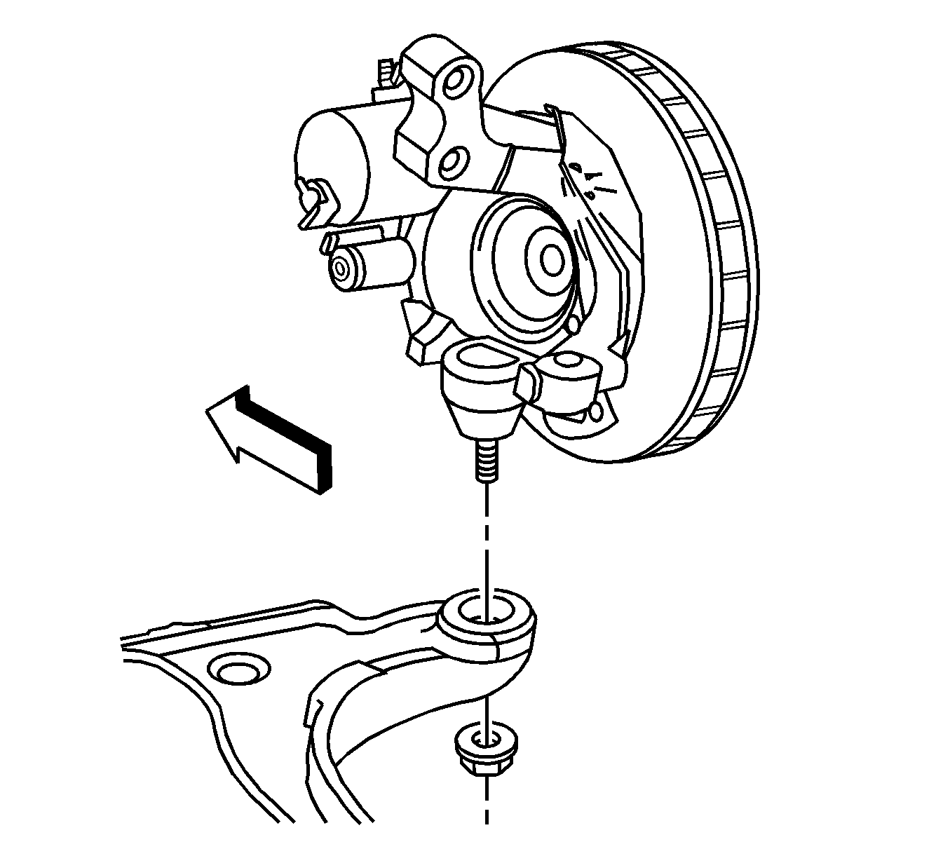
- Install the ball joint to steering knuckle. Refer to Lower Control Arm Ball Joint Replacement.
- Install the ball joint retaining nut.
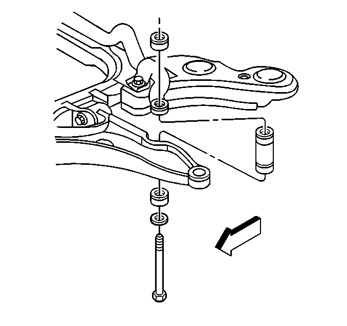
- Loosely install the right and left stabilizer shaft insulators, brackets, and bolts.
- Loosely install the stabilizer link insulators, washers, nut, and bolt.
- Install the tie rod to steering knuckle.
- Install the cotter pin in tie rod ends.
- Install the front wheels and tires. Refer to Tire and Wheel Removal and Installation.
- Lower the vehicle.
Caution: Refer to Fastener Caution in the Preface section.
Tighten
Tighten the ball joint retaining nut to 30 N·m (22 lb ft) plus an additional 210 degrees.


Tighten
| • | Tighten the stabilizer bracket bolts to 50 N·m (37 lb ft). |
| • | Tighten the stabilizer link nut to 23 N·m (17 lb ft). |
| • | Tighten the tie rod end to knuckle nut to 30 N·m (22 lb in) plus an additional 200 degrees. |
Stabilizer Shaft Replacement FE1 and FE3
Special Tools
J 24319-B Universal Steering Linkage Puller
Removal Procedure
- Raise and support the vehicle. Refer to Lifting and Jacking the Vehicle.
- Remove the front wheels and tires. Refer to Tire and Wheel Removal and Installation.
- Remove the stabilizer shaft links. Refer to Stabilizer Shaft Link Replacement.
- Remove the stabilizer shaft insulators. Refer to Stabilizer Shaft Insulator Replacement.
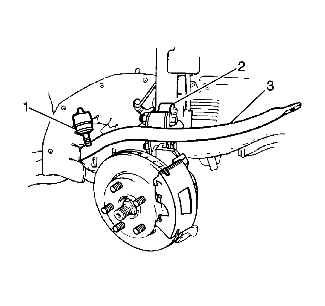
- Remove the left outer tie rod end retaining nut.
- Using J 24319-B disconnect the outer tie rod end from the steering knuckle.
- Remove the exhaust manifold pipe. Refer to Exhaust Manifold Rear Pipe Replacement.
- Turn the left strut completely to the left. Guide the stabilizer shaft out the left side of the vehicle between the axle and the lower control arm.
- Remove the stabilizer shaft (3) out from under the vehicle.

Installation Procedure
- Install the stabilizer shaft (3) to the vehicle.
- Install the exhaust manifold pipe. Refer to Exhaust Manifold Rear Pipe Replacement.
- Loosely install the following components:
- Install the stabilizer shaft links. Refer to Stabilizer Shaft Link Replacement.
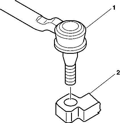
- Install the left tie rod end (1) to the steering knuckle.
- Install the left outer tie rod retaining nut.
- Install the front wheels and tires. Refer to Tire and Wheel Removal and Installation.
- Lower the vehicle.

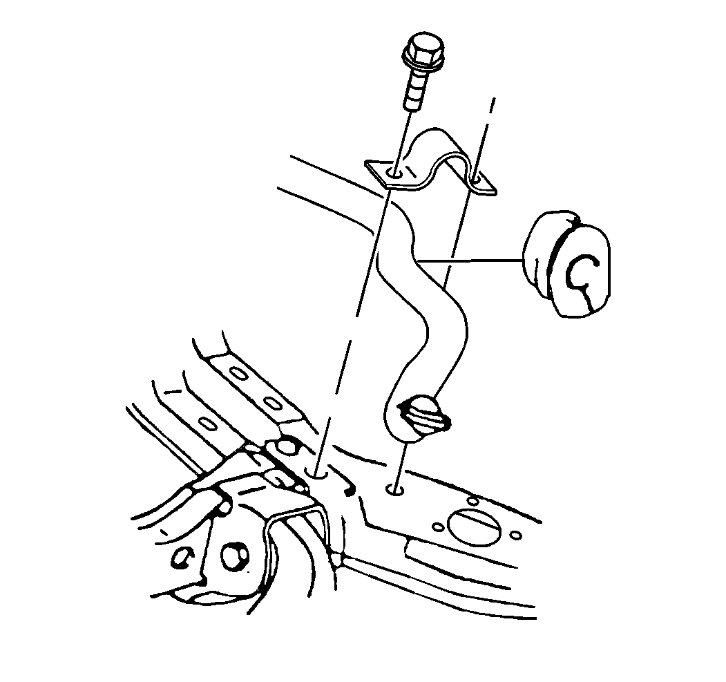
| 3.1. | The left and right stabilizer shaft insulators |
| 3.2. | The brackets |
| 3.3. | The bolts |
Caution: Refer to Fastener Caution in the Preface section.
Tighten
| • | Tighten the stabilizer shaft insulator bracket bolts to 33 N·m (24 lb ft). |
| • | Tighten the outer tie rod end to steering knuckle to 30 N·m (22 lb ft) + 200 degrees. |
