Shock Absorber Replacement FE7
Removal Procedure
- Raise the vehicle and suitably support. Refer to Lifting and Jacking the Vehicle.
- Remove the wheel and the tire. Refer to Tire and Wheel Removal and Installation.
- Support the lower control arm with a jack.
- Disconnect the electronic level control air tube from the shock.
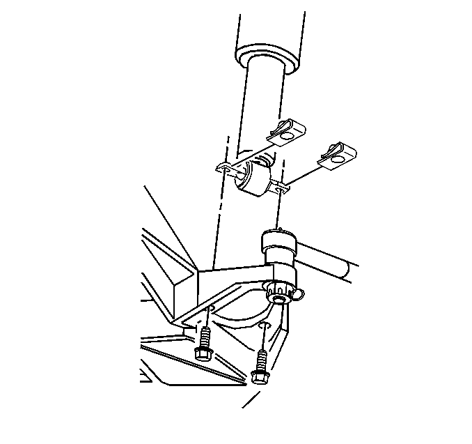
- Remove the 2 bolts securing the shock to the control arm.
- Pull the trunk trim back to gain access to the upper shock.
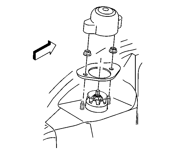
- Remove the upper shock dust cover.
- Remove the 2 nuts and the reinforcement from the shock.
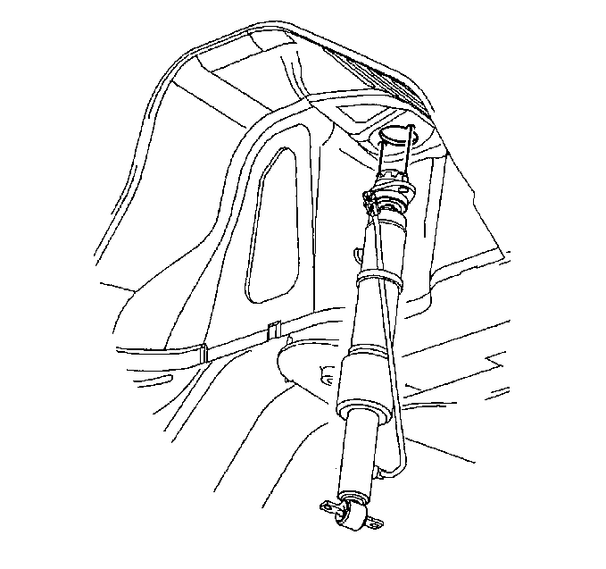
- Remove the shock from the vehicle.


Installation Procedure
- Install the shock on the vehicle.
- Install the shock upper mount.
- Install the shock reinforcement and the 2 nuts.
- Install the shock cover.
- Position the trunk trim in the proper location.
- Install the lower shock bolts.
- Connect the electronic air control air tube to the shock.
- Install the wheel and the tire. Refer to Tire and Wheel Removal and Installation.
- Lower the vehicle.


Caution: Refer to Fastener Caution in the Preface section.
Tighten
Tighten the nuts to 25 N·m (18 lb ft).

Tighten
Tighten the bolts to 25 N·m (18 lb ft).
Tighten
Tighten the wheel nuts to 125 N·m (80 lb ft).
Note: Before lowering the vehicle onto its wheels, or before driving the vehicle if it was not on a lift, turn the ignition ON and wait approximately 45 seconds. This will permit the automatic level control (ALC) system to execute the ARC, ensuring that the air adjustable shock absorbers are filled with residual pressure.
Shock Absorber Replacement FE1, FE3
Removal Procedure
- Raise the vehicle and suitably support. Refer to Lifting and Jacking the Vehicle.
- Remove the wheel and tire. Refer to Tire and Wheel Removal and Installation.
- Support the lower control arm with a jack.
- Disconnect the electronic level control air tube from the shock.
- Disconnect the shock electrical connector and remove the wiring from the control arm.
- Remove the 2 bolts securing the shock to the control arm.
- Pull the trunk trim back to gain access to the upper shock.
- Remove the upper shock dust cover.
- Remove the 2 nuts and the reinforcement from the shock.
- Remove the shock from the vehicle.


Installation Procedure
- Install the shock on the vehicle.
- Install the shock upper mount.
- Install the shock reinforcement and the two nuts.
- Install the shock cover.
- Position the trunk trim in the proper location.
- Install the lower shock bolts.
- Connect the electronic air control air tube to the shock.
- Connect the electrical connector and route the wiring on the control arm (FE3 and FE45).
- Install the wheel and the tire. Refer to Tire and Wheel Removal and Installation.
- Lower the vehicle.


Caution: Refer to Fastener Caution in the Preface section.
Tighten
Tighten the nuts to 25 N·m (18 lb ft).

Tighten
Tighten the bolts to 25 N·m (18 lb ft).
Tighten
Tighten the wheel nuts to 125 N·m (80 lb ft).
Note: Before lowering the vehicle onto its wheels (or before driving the vehicle, if it was not on a lift) turn the ignition ON and wait approximately 45 seconds. This will permit the ALC system to execute the ARC, ensuring that the air adjustable shock absorbers are filled with residual pressure.
