UNSTABLE IDLE,CODE 30 LOW ISC CORRECT ISC SETTING PROCEDURE

MODELS AFFECTED: 1985 FWD DEVILLE AND FLEETWOOD
This bulletin supersedes Serviceman Bulletin T-84-93, Group 6C, which should be destroyed.
The first revision of the 1985 FWD Deville/Fleetwood Service Information Manual includes a revised procedure for adjustment of the Idle Speed Control (ISC). Due to differences in how the ECM controls ISC, "tricking" the ISC to retract the plunger as described in the original Service Manual procedure will not completely retract the plunger. This will cause an incorrect ISC setting with the plunger gap being too large, possibly resulting in an unstable idle, Code E30, low idle speed operation, or a condition in which the ISC ratchets at cold ambients or with high accessory loads.
To prevent the possibility of misadjustment due to use of the incorrect service procedure, please verify that your Service Manual has been updated. The revised looseleaf pages do not contain a revision number and date; however, since Section 6E was reprinted in its entirety, page 6E-1 should say "revised section 4/30/84". The procedure is on pages 6E-55 through 6E-58 of Section 6E as revised. If the procedure is not found on these pages, your Service Manual does not contain revision 1. Revision 1 can be obtained from Helm Incorporated, Post Office Box 3617, Highland Park, Michigan 48203.
The Minimum Air, Throttle Position Sensor and ISC Motor Adjustment procedure from revision 1 is reprinted below in its entirety, with changes from the original procedure indicated by shading.
Minimum Air, Throtyle Position Sensor and ISC Motor Adjustments
1. Enter diagnostic mode and record all trouble codes displayed (numbers displayed between the time "1.8.8" is displayed and ".7.0" is displayed). If no codes are displayed, proceed to step 2. If codes are displayed, refer to the heading "Diagnosis Procedure" in Section 8D. When this diagnosis is completed, proceed with step 2.
2. While in the diagnostic mode and with ".7.0" displayed, perform the switch tests as described previously in this Section. Refer to Section 8D1 for the appropriate diagnosis for codes which do not pass.
3. Remove the air cleaner, plug the THERMAC vacuum tap, start the engine, and warm the engine up to normal operating temperature (parameter P.O.4 greater than 85 DEG C). Turn A/C off. Check engine timing using fixed spark mode as described previously in this Section. Adjust to specification if needed (see Section 6D HT4100 for procedure).
4. Turn off all electric accessories. The cooling fans must not be running. If the fan is running, let engine cool until fans turn off. Place steering wheel in its center position. Place the transmission in Park.
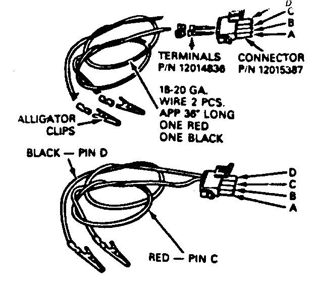
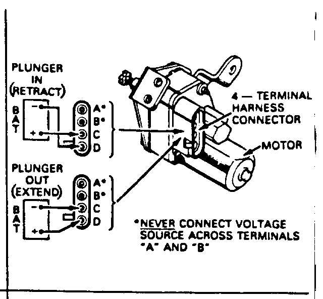
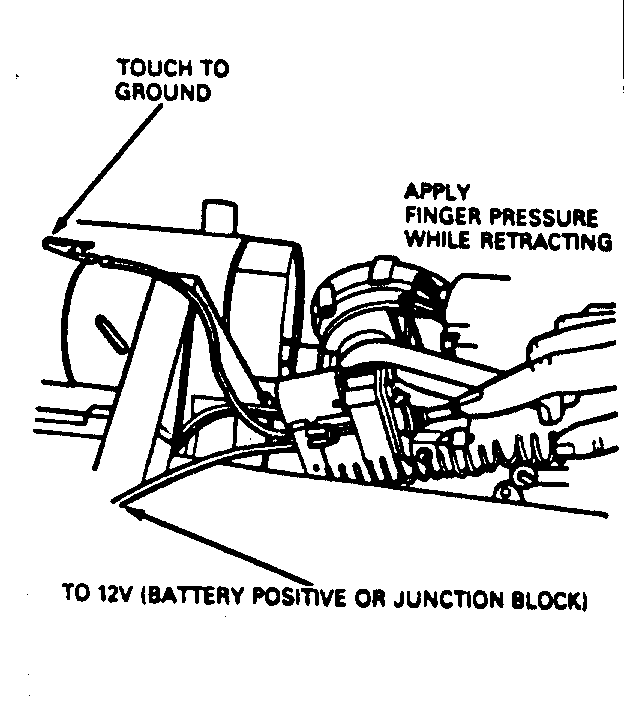
5. Retract the ISC motor plunger by applying external power with "Idle Speed Control Motor Tester" tool J34025 or equivalent or by using the jumper harness procedure shown in Figure 1.
IMPORTANT: "Tricking" the ISC to retract as in past model years will not retract the ISC fully on the FWD "C". Software in the FWD "C" will cause the ISC to stop retracting at an inderterminate position instead of with the plunger fully seated. If the plunger is not fully seated, the gap setting (Step 15) could result in a gap that is too large causing ISC "ratcheting" at cold ambient temperatures or high accessory loads.
NOTICE:
To prevent internal damage to the ISC, apply finger pressure to the ISC plunger while retracting. Retracting the ISC without pressure on the plunger may cause the internal gears to clash and bind.
Do not leave external voltage applied to the ISC for longer than necessary to seat the ISC plunger. If the motor is stalled retracted for prolonged periods, damage to the ISC motor will result.
Never connect a voltage source to terminals "A" and "B" as damage to the internal throttle switch contacts will result.
6. With the ISC plunger fully retracted, the plunger should not be touching the throttle lever. If contact is noted, adjust the ISC plunger (turn in) with pliers or available special Tool J-29607 so that it is not touching the throttle lever.
7. If in diagnostics, exit by depressing "AUTO". Depress the "OFF" button and wait 10 seconds before entering diagnostics to deenergize the A/C clutch. Enter diagnostics and observe the "OUTSIDE TEMP" light. The light should be off to indicate that the A/C clutch is not energized. Display engine data parameter P.1.1 and observe engine speed at minimum air. If the vehicle has under 500 miles and the displayed engine speed is "30" to "50" then proceed to step 9. If the vehicle has over 500 miles and the displayed value is "40" to "50", proceed to step 9.
IMPORTANT: If engine speed is not with the above limits (too high), check for vacuum leaks at the throttle body, intake manifold, vacuum fittings, tees and hoses. If the minimum air setting is made with a vacuum leak present, fuel control can be adversely affected throughout the driving range.
8. If the engine speed value does not fall within the above limits, then connect a tachometer to the engine and adjust the throttle stop screw to obtain 450 RPM. If the engine speed cannot be corrected, check that the throttle is not held off the minimum stop screw because of linkage binding and interference with the ISC motor plunger. Also check vacuum hoses for leaks, for air leaks at throttle body mounting and intake manifold.
9. With the vehicle at ignition on (engine off), enter diagnostics and display engine data parameter P.0.1. Open the throttle and let it snap fully shut against the throttle stop screw. If the displayed throttle angle value is "O", proceed to step 15.
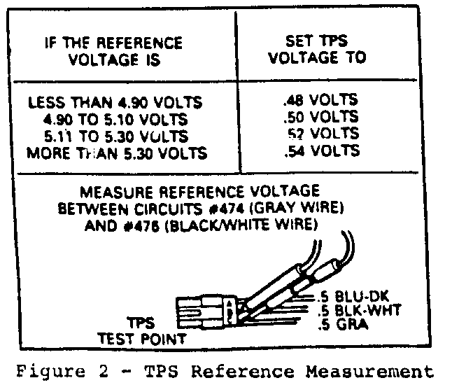
10. If the throttle angle value is not "O", backprobe the TPS test point circuit #474 (gray wire) terminal "C" and circuit #476 (black/white wire) terminal "B" using a digital voltmeter J-29125 or equivalent, Figure 2. Record the reference voltage for use in setting TPS
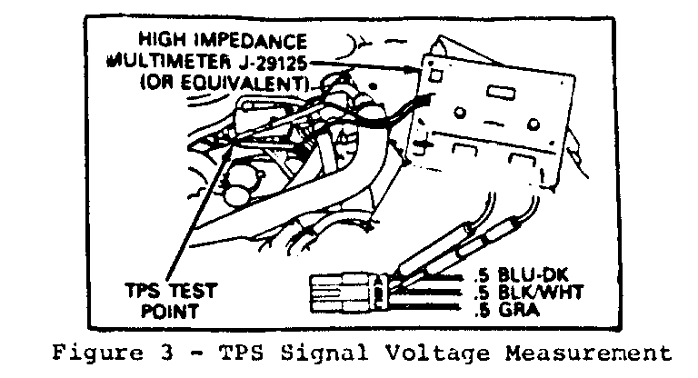
11. Connect a digital voltmeter to the TPS harness test point as follows (see Figure 3):
a. Ignition on, engine off. b. (+) lead to the TPS harness test point circuit #417 (dark blue wire) terminal "A". c. (-) lead to the TPS barness test point circuit #476 (black/white wire) terminal "B". d. Set the voltmeter on the 2-volt DC scale.
12. With the throttle fully shut against the throttle stop screw, check the voltmeter reading. If the TPS voltage is within .05 volts of the value shown in Figure 2, proceed to step 15.
13. If the TPS voltage does not fall within the above specification, losoen the TPS attachment screws just enough to permit rotation of the sensor. With the throttle fully shut against the throttle stop screw, position the TPS so that the voltmeter reads as shown in Figure 2.
14. Tighten the TPS mounting screws with the sensor in this position. Recheck the voltmeter reading to make sure that the adjustment remained within .05 volts of the TPS setting in step 13.
IMPORTANT: Do not use excessive force to adjust the TPS or damage may occur.
15. With the ISC motor fully retracted and the throttle fully shut against the throttle stop screw, measure the gap between the ISC motor plunger and the throttle lever. If the gap is .170-.140 inches (4.3-3.6mm), gap is OK; do not adjust. If the gap requires adjustment, reset to .160-.150 inches (4.1 - 3.8mm).
16. After verifying or adjusting the ISC plunger to throttle lever gap, extend the motor using J-34025 or equivalent, or as described in the jumper harness procedure, Figure 1. If ISC appears jammed in the fully retracted position, it may be necessary to apply and release ground several times, to "bump" the ISC from its stalled retracted position.
17. Disconnect all test equipment and reconnect all connections. Turn ignition off for at least 10 seconds. Start engine and check the ISC motor for proper operation.
18. The above procedure may have turned on a "Service" telltale light and/or may have set a trouble code. After the system is restored to its normal operation, the "Service" telltale light will go out but the trouble code will remain as an "intermittent" problem. Enter diagnostics, clear the stored codes, and turn the ignition off for at least 10 seconds.
General Motors bulletins are intended for use by professional technicians, not a "do-it-yourselfer". They are written to inform those technicians of conditions that may occur on some vehicles, or to provide information that could assist in the proper service of a vehicle. Properly trained technicians have the equipment, tools, safety instructions and know-how to do a job properly and safely. If a condition is described, do not assume that the bulletin applies to your vehicle, or that your vehicle will have that condition. See a General Motors dealer servicing your brand of General Motors vehicle for information on whether your vehicle may benefit from the information.
