QUARTZ SPEEDOMETER EXCHANGE PROGRAM

VEHICLES AFFECTED: 1985 Cadillac 'C' Models
The 1985 FWD Deville and Fleetwood standard quartz speedometer cluster in serviceable as an exchange unit (refer to Bulletin 8-131). Whenever this cluster is exchanged, it will be necessary to remove the odometer from the original cluster and transfer it to the replacement cluster. When this is required, the following procedure should be used:
1. Remove the inoperative cluster following the Service Information Manual procedures on page 8C-20 of the 1985 FWD Deville and Fleetwood Service Manual.
2. Remove the two (2) illumination bulbs from the gear selector indicator.
3. Remove the two (2) screws attaching gear selector indicator to the cluster housing and remove the gear selector indicator from the housing.
4. Disconnect the flex circuit connector from the internal circuit board.
5. Remove the six (6) screws attaching the clear lens to the housing. Remove the lens and black bezel.
6. Separate the housing from the black (speedometer face) component board by lifting the board straight off the lower dowel pins.
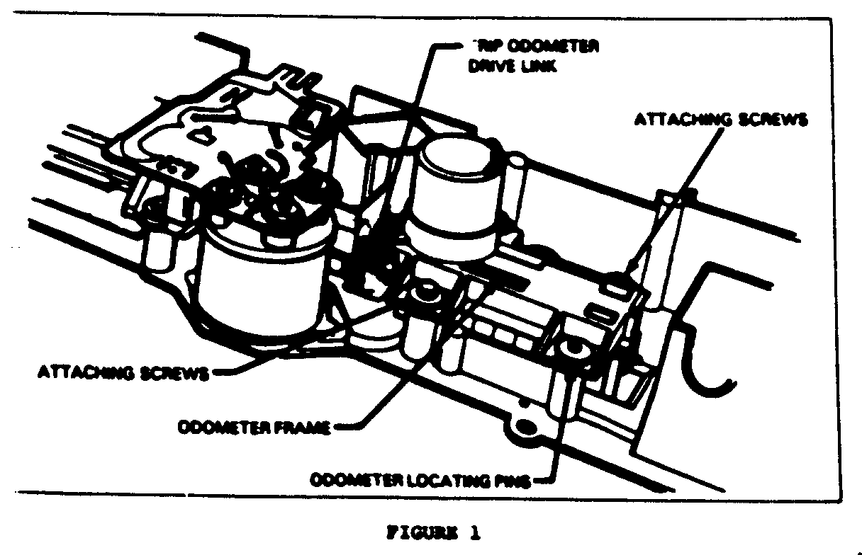
7. Turn the component board over and remove the two screws attaching the odometer frame to the housing. See Figure 1.
8. Before removing the odometer frame from the housing, grasp the drive link (see figure) with needle nose pliers to keep the link attached to the trip odometer. Remove the odometer frame with the drive motor attached. The plier grip can be released and the drive link will remain in place.
9. Turn tbe odometer frame over and remove the retaining clip from one end of the odometer shaft. With the clip removed, slide the odometer assembly toward the clip end and remove the odometer from the frame.
10. Reinstall the odometer frame into the inoperative cluster.
11. Install the replacement cluster:
11. Remove the two (2) screws securing odometer frame to the component board of the replacement cluster and separate.
12. Install the odometer assembly into the frame and replace the retaining clip. Note the position of the groove in the odometer assembly and rotate the trip odometer drive link to that position before installing the odometer frame onto the component board. To reinstall the odometer assembly onto the component board, engage the drive link with the groove of the odometer assembly and slide the odometer assembly onto the drive link and locating pins of the component board.
13. Reinstall the odometer frame to the component board with two (2) attaching screws.
14. Reinstall the black (speedometer face) component board locating it on the dowel pins.
15. Reinstall the black bezel and lens and secure with the six (6) attaching screws.
16. Connect the flex circuit connector to the internal circuit board.
17. Reinstall the gear selector indicator using the two (2) attaching screws.
18. Reinstall the two gear selector indicator illumination bulbs.
19. Reinstall the cluster assembly following the Service Manual procedures on page 8C-21.

General Motors bulletins are intended for use by professional technicians, not a "do-it-yourselfer". They are written to inform those technicians of conditions that may occur on some vehicles, or to provide information that could assist in the proper service of a vehicle. Properly trained technicians have the equipment, tools, safety instructions and know-how to do a job properly and safely. If a condition is described, do not assume that the bulletin applies to your vehicle, or that your vehicle will have that condition. See a General Motors dealer servicing your brand of General Motors vehicle for information on whether your vehicle may benefit from the information.
