HARSH SHIFT ALL GEARS LOSS OF VACUUM

VEHICLES AFFECTED: 1985 Vehicles Equipped With THM 440-T4 Transmissions
This bulletin is intended to assist the technician when diagnosing vacuum related shift conditions. For proper operation, the THM 440-T4 requires 44-57kPa (13-17 in. Hg) of engine vacuum at engine idle. A loss of engine vacuum can cause any of the following shift conditions:
Harsh park to reverse engagement Harsh neutral to drive engagement Harsh or firm light throttle upshifts 2nd speed starts Harsh 3-2 coastdown shifts Rough 4-3 & 3-2 manual downshifts Slipping in drive or reverse
Low engine vacuum can be caused by a pinched, cut, plugged or disconnected vacuum line. It can also be the result of a poorly tuned-engine or blocked exhaust. Also an incorrectly installed aspirator tee can give the appearance of low vacuum when the air conditioning is in operation. The aspirator tee has a 'flag' with the words 'MOD' and 'MAN.'. Make certain the modulator line is connected to the 'MOD.' nipple, and the manifold line is connected to the "MAN.' nipple as indicated by the arrows on the flag.
To check for proper vacuum, disconnect the vacuum line at the modulator and install a vacuum gauge to the line. If there is insufficient vacuum locate the cause and correct as required.
If there is sufficient engine vacuum available to the modulator, remove the modulator assembly and modulator valve. Inspect the valve for nicks or scoring. Connect a hand operated vacuum device (vacuum pump) to the modulator. Pump the device until 51-68kPa (15-20 in. Hg) of vacuum is reached; at the same time, observe the modulator plunger, it should be drawn in as the vacuum pump is operated. After reaching 51-68kPa (15-20 in. Hg) the vacuum should not bleed down for at least 30 seconds.
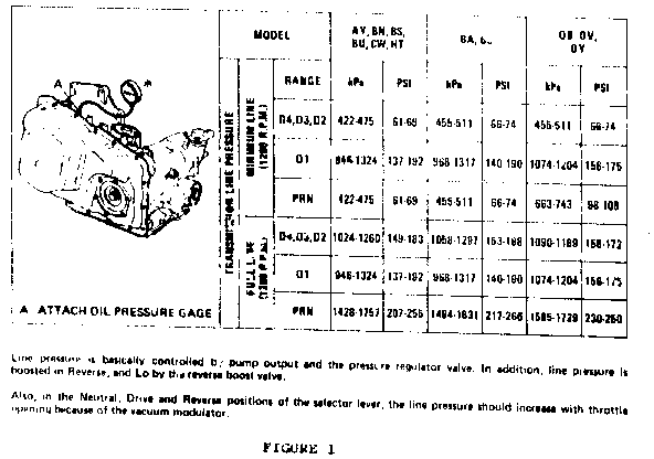
If the modulator is found to be functioning properly and the valve is not damaged the shift problem is not vacuum related. At this time attach an oil pressure gauge to the pressure tap as illustrated in Figure 1. Note the pressures and refer to diagnosis section in the service manual. As a reminder the T.V. does not control line pressure; it is used to control shift points (shift speed) only. An updated oil pressure chart (Figure 1) is attached, which replaces the oil pressure chart in the service manual.
PRELIMINARY CHECK PROCEDURE
CHECK TRANSMISSION OIL LEVEL CHECK AND ADJUST T,V. CABLE CHECK OUTSIDE MANUAL LINKAGE AND CORRECT CHECK ENGINE TUNE INSTALL OIL PRESSURE GAGE* CONNECT TACHOMETER TO ENGINE CHECK OIL PRESSURES IN THE FOLLOWING MANNER
Minimum Line Pressure Check
With the brakes applied, take the line pressure readings in the ranges and at the engine r.p.m.'s indicated in the chart below.
Full Line Pressure Check
Full line pressure readings are obtained by removing the vacuum line from modulator, and with the brakes applied, take the line pressure readings in the ranges and at the engine r.p.m.'s indicated in the chart below.
Line pressure is basically controlled by upump output and the pressure regulator valve. In addition, line pressure is boosted in Reverse, and Lo by the reverse boost valve.
Also, in the Neutral, Drive and Reverse postions of the selector lever, the line pressure should increase with throttle opening because of the vacuum modulator.

General Motors bulletins are intended for use by professional technicians, not a "do-it-yourselfer". They are written to inform those technicians of conditions that may occur on some vehicles, or to provide information that could assist in the proper service of a vehicle. Properly trained technicians have the equipment, tools, safety instructions and know-how to do a job properly and safely. If a condition is described, do not assume that the bulletin applies to your vehicle, or that your vehicle will have that condition. See a General Motors dealer servicing your brand of General Motors vehicle for information on whether your vehicle may benefit from the information.
