POWER STEERING PUMP NOISE RELOCATE FLUID RESERVOIR

VEHICLES AFFECTED: 1985 'C' and 'D' Models
Some 1985 Front Wheel Drive Devilles and Fleetwoods built prior to B.C. no. 286346 may exhibit a 'moaning' or 'groaning' noise from the power steering pump upon cold start in cold ambient temperatures below -7 degrees C (20 degrees F). This noise may continue for up to two minutes after engine startup.
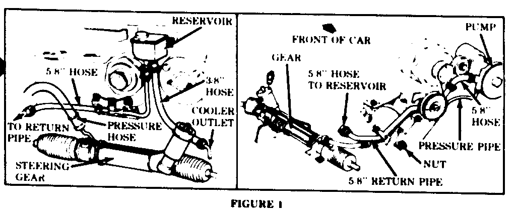
Information in this bulletin applies only to vehicles with the power steering fluid reservoir located on the cowl near the brake booster, as shown in Figure 1. If such a condition is encountered on cars with the power steering fluid reservoir located on the tensioner support next to the power steering pump, refer to 1985 Deville and Fleetwood Service Information Manual Section 3 for diagnosis.
This noise may be caused by fluid cavitation in the power steering pump. This condition may be eliminated by converting the early model power steering system to the later design with the fluid reservoir located on the tensioner bracket. The parts necessary to make this conversion a re available through GM Parts and are listed below.
Description Part Numbers ----------- ------------ Reservoir 7849151 Reservoir Cap 7848931 Return Pipe 1631883 Support (Tensioner Brkt.) 1636472 A.I.R. Pipe 1633811 15.88mm (5/8in.) Return Hose (Pre-Formed) 1631383 9.53mm (3/8in.) Return Hose (Pre-Formed) 1631384 Bolt (2 Req'd) 11508600 Screw (2 Req'd) 11508797 9.53mm (3/8in.) Hose Clamps (2 Req'd) 25518880
All parts included in the above list must be installed when performing the conversion to ensure that the return pipe assembly is properly retained. The following procedure should be used for installation.
1. Loosen serpentine belt and position out of the way.
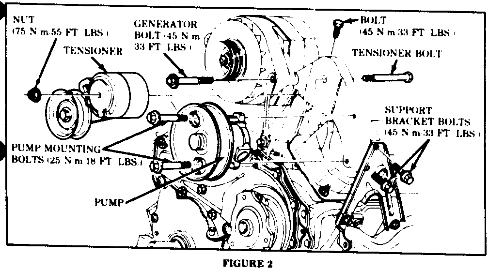
2. Remove tensioner nut and bolt from the support and remove tensioner. See Figure 2.
3. Remove the 15.88mm (5/8in.) return hose clamps at the power steering pump and the upper end of the 15.88mm (5/8in.) return pipe. Remove and discard the short section of 15.88mm (5/8in.) hose. Keep the hose clamps for use later in this procedure. See Figure 1.
4. Remove both power steering pump mounting bolts. It is not necessary to remove the steering pressure pipe from the pump fitting or to remove the pump from the car. See Figure 2.
5. Remove the tensioner and power steering pump support from the engine. Refer to Figure 2. Install the new suport and tighten mounting bolts to 45 N.m (33 ft. lbs.).
6. Remove all power steering fluid from the reservoir. Remove clamps and hoses from reservoir. Remove reservoir mounting nut and remove reservoir from car. See Figure 1.
7. Loosen A/C accumulator bracket clamp bolt and remove the A/C suction hose retainer at the radiator. Reposition the A/C suction hose to gain additional clearance at the right side of the engine.
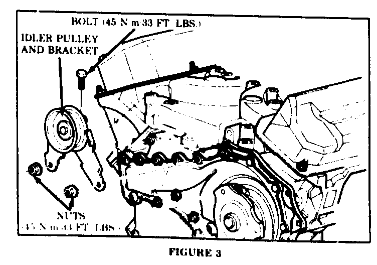
8. Remove the idler pulley bracket from its mounting on the engine block and intake manifold as shown in Figure 3. It is not necessary to remove the idler pulley from the pulley bracket.
9. Remove the 15.88mm (5/8in.) power steering return pipe retaining nut from the right side of the engine, Figure 1.
10. Raise car. Remove power steering return hoses from the cooler pipe outlet and the lower end of the 15.88mm (5/8in.) return pipe. Allow fluid to drain from the system.
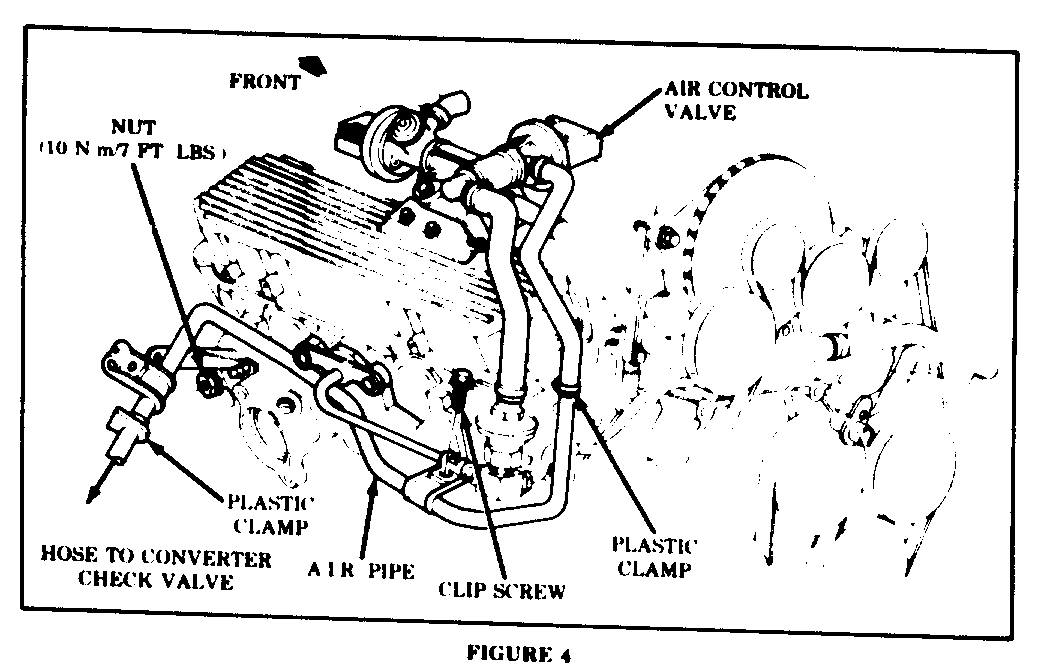
11. Remove plastic hose retainers and hoses from both ends of the A.I.R. pipe which extends from the catalytic check valve to the A.I.R. control valve hose. See Figure 4. Remove the pipe and install the new A.I.R. pipe.
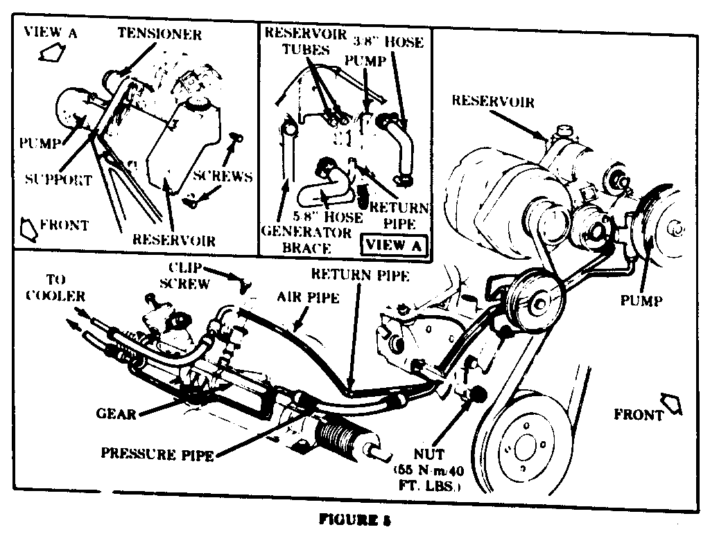
12. From beneath the car, position the new return pipe along the right side of the engine and install retainer screw on the A.I.R. pipe weld clip, Figure 5.
13. Using the 9.53mm (3/8in.) return hose removed from the cooler outlet, cut a 30.5cm (12in.) length of hose and install between the cooler outlet and the new return pipe. Install one 9.53mm (3/8in.) hose clamp at each end and tighten.
14. Lower car. Ensure that new return pipe is correctly positioned along the right side of the engine as shown in Figure 5 and install pipe retainer nut on engine block stud. Tighten nut to 55 N.m (40 ft. lbs.).
15. Install idler pulley bracket and tighten fasteners to 45 N.m (33 ft. lbs.). Reposition A/C suction line, install line retainer and tighten accumulator clamp.
16. Position tensioner mounting bolt and install new reservoir on tensioner support. Install 15.88mm (5/8in.) and 9.53mm (3/8in.) formed hoses as shown on Figure 5. Ensure that the 15.88mm (5/8in.) hose is positioned between the generator brace and the support and does not interfere with tensioner pulley.
17. Install pump mounting bolts and tighten to 25 N.m (18 ft. lbs.).
18. Install tensioner and tighten nut to 75 N.m (55 ft. lbs.). Install serpentine belt.
19. Fill and bleed power steering system as outlined in the 1985 Deville and Fleetwood Service Information Manual Section 3B1. Inspect entire system for leaks and ensure that all pipes and hoses are properly positioned.
General Motors bulletins are intended for use by professional technicians, not a "do-it-yourselfer". They are written to inform those technicians of conditions that may occur on some vehicles, or to provide information that could assist in the proper service of a vehicle. Properly trained technicians have the equipment, tools, safety instructions and know-how to do a job properly and safely. If a condition is described, do not assume that the bulletin applies to your vehicle, or that your vehicle will have that condition. See a General Motors dealer servicing your brand of General Motors vehicle for information on whether your vehicle may benefit from the information.
