SPECIAL POLICY: LAMP ADDITION HIGH MOUNTED STOP LAMP

VEHICLES AFFECTED: 1985 Front-wheel-Drive (FWD) DeVilles and Fleetwoods
In the fall of 1984 a sales merchandising activity featured the Centre High-mounted Stop Lamp as standard equipment on all 1985 FWD DeVilles and Fleetwoods. Production of this feature was to have begun Septemer 4, 1984 but unfortunately, sufficient parts were not available until November 19, 1984.
As a result, Dealer invoices for 1985 FWD DeVilles and Fleetwoods assembled from September 4 through November 19 reflected a $26.73 credit to account for absence of the Centre High-mounted Stop Lamp feature.
SPECIAL POLICY ADJUSTMENT
This Special Policy makes the Centre High-mounted Stop Lamp available to all owners of 1985 FWD DeVilles and Fleetwoods, per the Vehicles Involved section of this bulletin.
Owners of vehicles built between September 4, 1984 and November 19, 1984 are eligible for the Centre High-mounted Stop Lamp at the previously credited $26.73 price. Owners of vehicles built before September 4, 1984 may purchase the Stop Lamp at the retail price.
DEALER INFORMATION
There are no time or mileage limitations on the provisions of this Special Policy but parts will not be available after August 31, 1987. The Special Policy Adjustment Bulletin should be filed in the three ring binder furnished to Dealers during September, 1982.
Owners of affected vehicles will not receive letters from General Motors of Canada; however, all 1985 FWD DeVilles and Fleetwoods are eligible for Stop Lamp installation, subject to the provisions in the Vehicles Involved and Credit sections of this Special Policy Adjustment Bulletin.
VEHICLES INVOLVED
Vehicles eligible for the Centre High-mounted Stop Lamp at the $26.73 credited price are within the following range: VIN F4245537 through VIN F4274838
Owners of vehicles prior to VIN F4245537 may purchase the Stop Lamp at the retail price.
PARTS INFORMATION
Parts required to complete this Special Policy should be obtained from the Parts Distribution Centres. The following parts are to be used:
Description Usage Part Number ----------- ----- ----------- Kit, Centre High Mounted 1985 FWD DeVille 16506254 Stop Lamp* and Fleetwood
* The kit includes three brackets and two pedestals to accommodate each rear deck shelf panel design.
SERVICE PROCEDURE
1. Using masking tape, cover an approximate 8 in. x 8 in. area on rear deck shelf trim near centreline of vehicle. Determine exact centreline of package shelf and mark this centreline on masking tape.
For cars equipped with rear window glass inserts (Fleetwood and cars equipped with vinyl roofs) remove pedestal attached to lamp assembly and install higher pedestal P/N 16504071 on lamp assembly.
Paint lamp assembly and pedestal to match interior colour of car.
2. Centre base of pedestal on centreline marked on taped area on rear deck shelf trim in Step 1. Position lamp assembly with rubber shroud contacting rear window glass (shroud will prevent light reflection into passenger compartment). Trace outline of lamp assembly pedestal on taped area in this position.
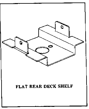
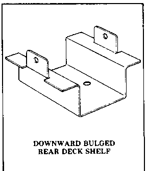
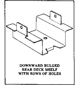
To determine which mounting bracket is required for the vehicle, open the trunk and look at the underside of the rear deck shelf panel:
If the rear deck shelf panel is flat in the area where the lamp assembly is to be located, use support No. 20557018 (shallow support with 1 in. hole in centre).
If the rear deck shelf panel has a bulge in the area where the lamp assembly is to be located, use support No. 20565299 (deeper support with no hole in centre, 1/2 in. hole must be drilled in centre of bracket).
If the rear deck shelf panel has a bulge in the area where the lamp assembly is to be located and has a plate with rows of holes in it attached to bulged area, use support No. 20565298 (deeper support with down-turned tabe at one edge, 1/2 in. hole must be drilled in centre of bracket).
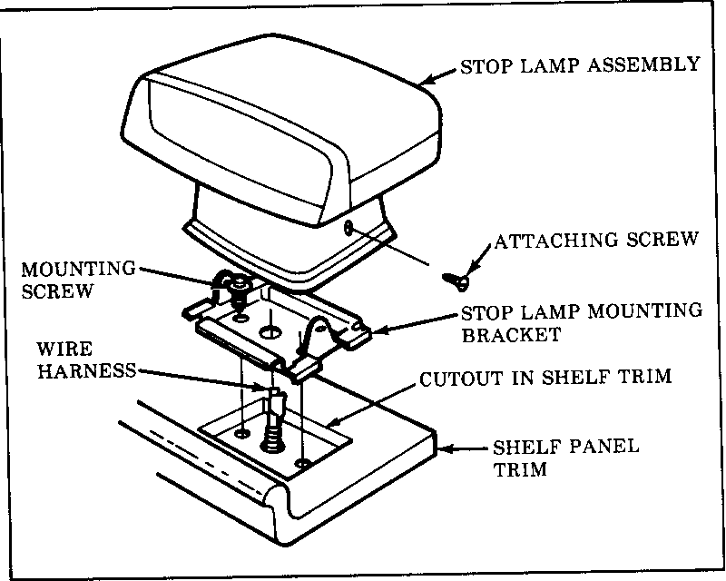
3. Once correct mounting bracket has been determined, position the mounting bracket inside the traced outline of pedestal in Step 2. Centre the mounting bracket side-to-side and front-to-back and trace outline of mounting bracket on tape. Using a sharp knife, cut and remove the rear deck shelf trim (including accoustic insulation) enclosed within the outline of the mounting bracket. Do not cut out the area enclosed by the base of the pedestal.
4. From inside the passenger compartment, place mounting bracket in area cut out in step 3 and mark the two bracket mounting holes and the centre hole in bracket on the rear deck shelf panel. From inside the passenger compartment, centre punch and drill the two 1/4 in. mounting holes, if required, and a 1/2 in. centre hole.
5. Secure mounting bracket to rear deck shelf using screws, washers and nuts provided in installation kit. Do not attach lamp assembly to mounting bracket at this time.
6. Carefully remove rear seat, rear seat back, and insulation pad behind rear seat. Drill 1/2 in. hole in sheet metal behind rear seat back. Hole is to be located on centreline of lamp assembly 2 in. below edge of rear deck shelf trim.
7. Install the connectorless end of the wire harness through the hole in rear seat back sheet metal and through the centre hole in the rear deck shelf. Install rubber grommet for hole in rear seat back sheet metal and inatall both wire ends in connector provided in kit. (Orientation of wires in connector is not critical.)
8. Route wire harness down right hand side of car to junction block located behind glove box. Harness is to be installed underneath carpeting. To accomplish this, carefully remove the seat belt retractor, lower 'B' pillar trim, right side sill plates and right hand kick panel. The harness should be placed underneath the carpet far enough so it does not interfere with trim when reassembling. Reinstall rear insulation pad, rear seat back, and rear seat.
9. Remove glove box for access to the junction block. Remove dark blue with white stripe jumper wire located in cavities J and K of the black 11 pin connector on the right side of the junction block. Install jumper harness from kit in cavities J and K of this same junction block connector and connect blue wire of centre high mount stop lamp harness to the jumber harness. The black wire of the centre high mount stop lamp harness should be plugged into the open 2 pin connector space located on the lower left side of the junction block connector. Reinstall glove box.
10. Test for proper operation of Centre high mounted stop light. The light should light when the brake pedal is depressed. The light should not light when turn signals are activated. The Dealer installed centre high mount stop lamp will flash with the hazard flashers. The factory installed stop lamp will not flash with the hazard flashers.
11. Remove remaining masking tape from rear deck shelf trim. Complete final installation of lamp assembly to mounting bracket using two sheet metal attaching screws provided in kit. To prevent light reflection into passenger compartment adjust the pedestal rearward until the rubber shroud of the lamp assembly is in contact with the rear window glass.
CREDIT
Credit will be issued upon receipt of a properly prepared warranty claim as follows:
1985 FWD DeVille and Fleetwood from VIN F4245537** to F4274838.
Labour Labour Net Item Operation Hours Dollar Amount* --------- ----- -------------- T6115 1.3 $ XX.XX
* The Net Item Dollar Amount should be the total of the current Dealer Net plus 30% of all parts required for the repair, minus $26.73 which is customer pay as noted in the Vehicles Involved section of this bulletin.
NOTE: Do not enter a parts count, failed part number or parts dollar amount in the claim submission. Zone authorization is not required for claims meeting the criteria outlined in this bulletin.
* * Owners of vehicles built prior to VIN F4245537 may purchase the Centre High-mounted Stop Lamp at retail price.


General Motors bulletins are intended for use by professional technicians, not a "do-it-yourselfer". They are written to inform those technicians of conditions that may occur on some vehicles, or to provide information that could assist in the proper service of a vehicle. Properly trained technicians have the equipment, tools, safety instructions and know-how to do a job properly and safely. If a condition is described, do not assume that the bulletin applies to your vehicle, or that your vehicle will have that condition. See a General Motors dealer servicing your brand of General Motors vehicle for information on whether your vehicle may benefit from the information.
