FUEL LINE VIB.;BUZZING NOISE LT.-MED. THROTTLE ACCELERATION

VEHICLES AFFECTED: 1985 FWD Deville And Fleetwood
Some 1985 FWD Deville and Fleetwood vehicles may experience a fuel line vibration or 'buzz' noise under light to medium throttle acceleration. This vibration is transmitted through the plastic retainers attached to the fuel feed and return lines.
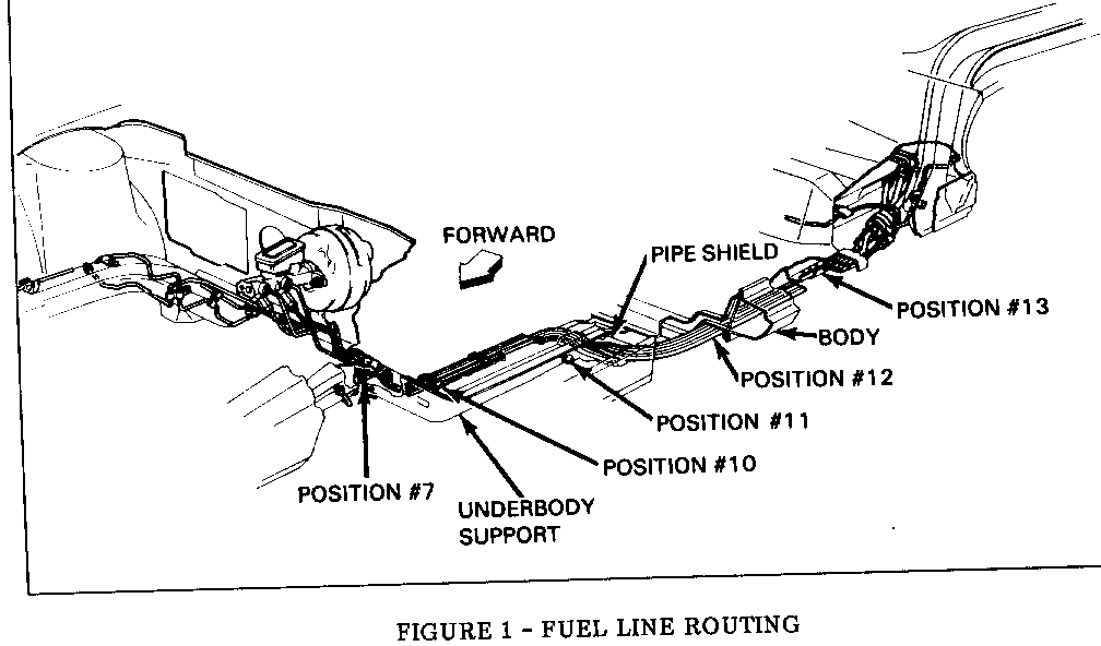
A fuel line isolator kit (P/N 1632307) is available through GMWDD to repair this condition. To determine if this isolator kit is needed to repair a fuel line noise condition, hoist the vehicle and examine the fuel line isolation mounting in the area indicated in Figure 1. If the vehicle already has the rubber isolation mountings included in the service kit and is exhibiting fuel line noise, inspect for fuel lines grounding against the underbody or underbody components and correct as necessary. If the vehicle has the plastic isolation mountings, install the isolator kit as follows:
1. Hoist vehicle.
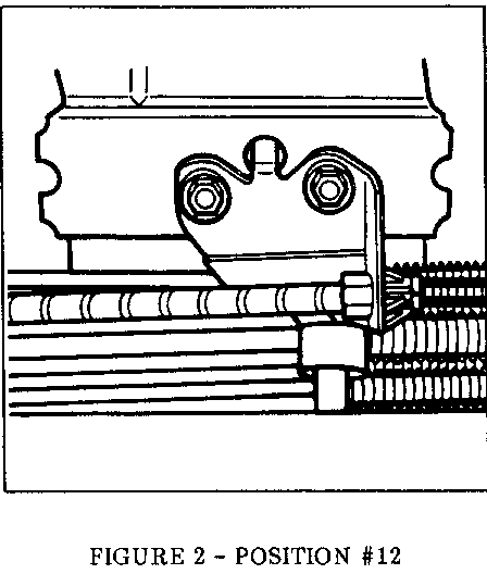
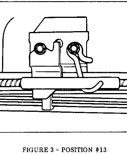
2. Remove both parking brake cable support brackets at underbody positions No. 12 and No. 13, see Figures 1, 2 and 3.
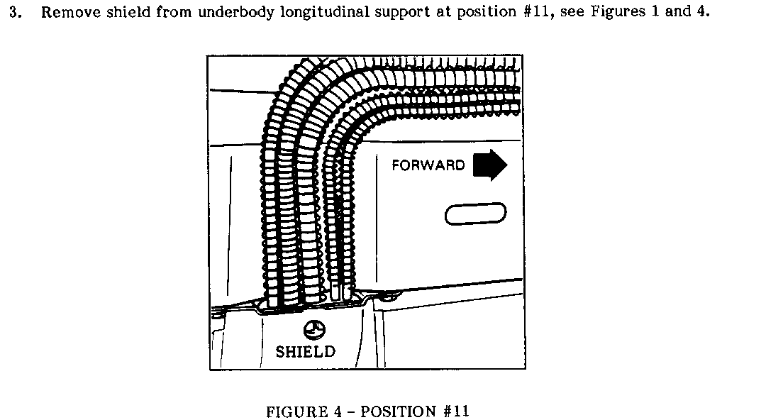
3. Remove shield from underbody longitudinal support at position No. 11, see Figures 1 and 4.
4. Using a suitable felt tip writing instrument or chalk, mark location of plastic retainers on fuel lines for use in steps 5 and 10. Do not scribe fuel lines. Remove plastic retainers from positions No. 11, No. 12 and No. 13 by attaching channel lock pliers to the plastic retainers, using a repeated rolling motion from front to rear of car, being careful not to nick or bend pipes. Discard clips.
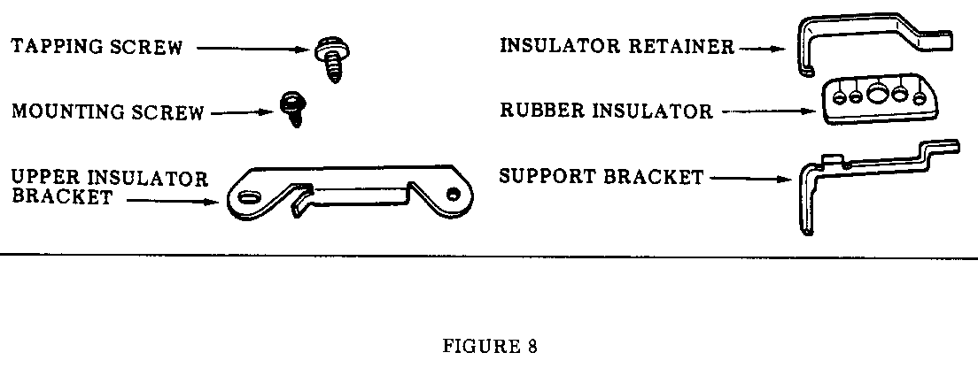
5. Install rubber insulators, see Figure 8 for part identifications, with slits up toward body floorpan, at positions No. 11, No. 12 and No. 13, see Figures 1,2, and 3. It may be convenient to use one wrap of friction tape over the rubber insulator to keep the insulators in place until the support brackets can be reinstalled.
Note: It may be necessary to slide stone guard coils on pipes either way from position No. 11 in order to install rubber insulator on pipes.
6. Reinstall parking brake cable support brackets which were removed in step No. 2, being careful to centre rubber insulator above bracket.
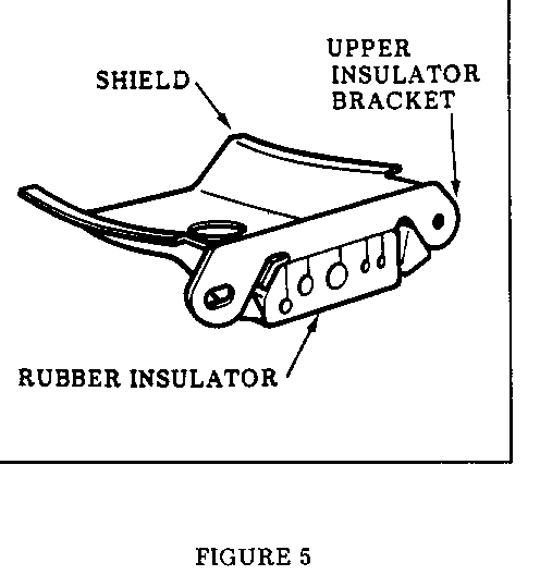
7. Reinstall shield to underbody at position No. 11, sandwiching rubber insulator between upper insulator bracket (contained in kit) and shield using original screws, see Figure 5. Apply upward pressure on shield while tightening bolts. Rubber insulator should be flush with inboard edge of shield.
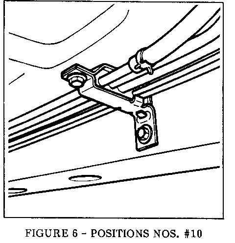
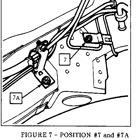
8. Remove and discard plastic retainers at positions No. 10, and No. 7 or 7A, whichever is applicable, see Figures 6 and 7. If retainer had been mounted at position No. 7 during vehicle assembly, reinstall brakeline clip using original mounting screw.
9. Remove and discard three plastic retainers located between position No. 11 and position No. 7. These three retainers are not replaced by any other isolators or retainers.
10. Install rubber insulator on pipes at positions No. 10 and No. 7A (see Figures 6 and 7) along with support bracket and insulator retainer using tapping screw included in kit, refer to Fiqure 8 for parts identification. Carefully align assemblies with holes in body longitudinal support. Install insulator support assemlies to body using original mounting screws.
NOTE: Support bracket at position No. 7A may need to have forward corner cut off to provide clearance to body longitudinal reinforcement.
11. Check alignment and clearance of all pipes to underbody and supports by applying light upward pressure to each pipe. If contact with floor pan is evident, correct as necessary to insure a totally insulated system.
12. Lower vehicle.
Use most applicable Labour Operation from Canadian Labour Time Guide and Claim 0.5 hours.
General Motors bulletins are intended for use by professional technicians, not a "do-it-yourselfer". They are written to inform those technicians of conditions that may occur on some vehicles, or to provide information that could assist in the proper service of a vehicle. Properly trained technicians have the equipment, tools, safety instructions and know-how to do a job properly and safely. If a condition is described, do not assume that the bulletin applies to your vehicle, or that your vehicle will have that condition. See a General Motors dealer servicing your brand of General Motors vehicle for information on whether your vehicle may benefit from the information.
