Exhaust Gas Recirculation Valve Replacement Valve
Removal Procedure
- Disconnect the electrical connector from the solenoid.
- Remove the fuel line bracket nut.
- Lift the fuel line bracket off the stud.
- Push fuel line bracket away from the EGR valve base.
- Remove the two mounting studs from the base of the EGR valve.
- Remove the EGR Valve.
- Clean the mounting surface for the EGR valve.
| • | Inspect the EGR passages in the crossover water pump housing for deposits. |
| • | Clean the EGR passages as needed. |
Installation Procedure
- Install cleaned or replacement EGR valve using a new gasket.
- Install the two mounting studs at base of EGR valve.
- Place the fuel line bracket onto the EGR valve stud.
- Install the fuel line bracket nut.
- Connect the electrical connnector to EGR solenoid.
Tighten
Tighten the 2 mounting bolts to 24 N·m (18 lb ft).
Refer to
Notice: Use the correct fastener in the correct location. Replacement fasteners must be the correct part number for that application. Fasteners requiring replacement or fasteners requiring the use of thread locking compound or sealant are identified in the service procedure. Do not use paints, lubricants, or corrosion inhibitors on fasteners or fastener joint surfaces unless specified. These coatings affect fastener torque and joint clamping force and may damage the fastener. Use the correct tightening sequence and specifications when installing fasteners in order to avoid damage to parts and systems.
in general information.Tighten
Tighten the 1 mounting nut to 24 N·m (18 lb ft).
Refer to
Notice: Use the correct fastener in the correct location. Replacement fasteners must be the correct part number for that application. Fasteners requiring replacement or fasteners requiring the use of thread locking compound or sealant are identified in the service procedure. Do not use paints, lubricants, or corrosion inhibitors on fasteners or fastener joint surfaces unless specified. These coatings affect fastener torque and joint clamping force and may damage the fastener. Use the correct tightening sequence and specifications when installing fasteners in order to avoid damage to parts and systems.
in general information.Exhaust Gas Recirculation Valve Replacement Pipe
Removal Procedure
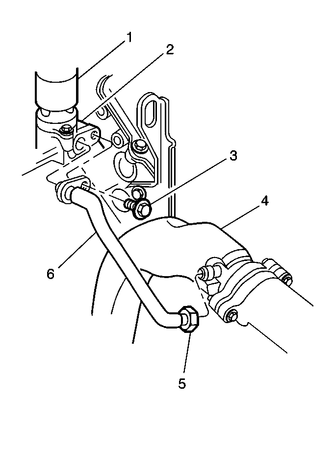
- Remove bolt at water pump housing (3).
- Raise and support the vehicle.
- Remove the Crossover Exhaust Pipe. Refer to Engine Mechanical .
- Remove the nut from Crossover Exhaust Pipe (5).
- Remove the EGR Valve Pipe (6).

Installation Procedure
- Install Crossover Exhaust Pipe. Refer to Engine Mechanical .
- Install EGR Pipe Nut to Crossover Exhaust Pipe (5).
- Lower the vehicle.
- Install bolt at waterpump housing (3).

Tighten
Tighten the EGR Pipe Nut to 60 N·m (44 lb ft).
Refer to
Notice: Use the correct fastener in the correct location. Replacement fasteners must be the correct part number for that application. Fasteners requiring replacement or fasteners requiring the use of thread locking compound or sealant are identified in the service procedure. Do not use paints, lubricants, or corrosion inhibitors on fasteners or fastener joint surfaces unless specified. These coatings affect fastener torque and joint clamping force and may damage the fastener. Use the correct tightening sequence and specifications when installing fasteners in order to avoid damage to parts and systems.
in general information.Tighten
Tighten the waterpump housing bolt to 24 N·m (18 lb ft).
Refer to
Notice: Use the correct fastener in the correct location. Replacement fasteners must be the correct part number for that application. Fasteners requiring replacement or fasteners requiring the use of thread locking compound or sealant are identified in the service procedure. Do not use paints, lubricants, or corrosion inhibitors on fasteners or fastener joint surfaces unless specified. These coatings affect fastener torque and joint clamping force and may damage the fastener. Use the correct tightening sequence and specifications when installing fasteners in order to avoid damage to parts and systems.
in general information.Exhaust Gas Recirculation Valve Replacement Water Pump Crossover Pipe
Removal Procedure
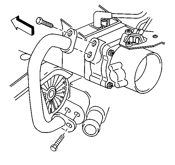
- Remove the water pump belt shield.
- Remove the bolt from throttle body spacer.
- Remove the fitting at the water pump crossover.
- Remove the EGR Water Pump Crossover Pipe.

Installation Procedure
- Install the fitting into water pump crossover.
- Install the bolt into the throttle body spacer.
- Install the water pump belt shield.

Tighten
Tighten the fitting to 24 N·m (18 lb ft).
Refer to
Notice: Use the correct fastener in the correct location. Replacement fasteners must be the correct part number for that application. Fasteners requiring replacement or fasteners requiring the use of thread locking compound or sealant are identified in the service procedure. Do not use paints, lubricants, or corrosion inhibitors on fasteners or fastener joint surfaces unless specified. These coatings affect fastener torque and joint clamping force and may damage the fastener. Use the correct tightening sequence and specifications when installing fasteners in order to avoid damage to parts and systems.
in general information.Tighten
Tighten the bolt to 24 N·m (18 lb ft). Refer
to
Notice: Use the correct fastener in the correct location. Replacement fasteners must be the correct part number for that application. Fasteners requiring replacement or fasteners requiring the use of thread locking compound or sealant are identified in the service procedure. Do not use paints, lubricants, or corrosion inhibitors on fasteners or fastener joint surfaces unless specified. These coatings affect fastener torque and joint clamping force and may damage the fastener. Use the correct tightening sequence and specifications when installing fasteners in order to avoid damage to parts and systems.
in general information.Exhaust Gas Recirculation Valve Replacement System Cleaning Procedure
Caution: Avoid breathing fumes and swallowing EGR exhaust deposits when removing components for cleaning as bodily injury may result.
Whenever the EGR valve is removed, or during regularly scheduled EGR system maintenance, the EGR system should be inspected and cleaned. This will insure that the EGR system will function properly under all operating conditions. Proper EGR system service consists of the following five steps:
- EGR System Diagnosis. Diagnosis of the EGR system should be performed if required by engine performance or engine driveability symptoms and no PCM DTCs are set .
- EGR Valve Pipe Cleaning and checking for leaks. Clean and check the EGR pipe from the exhaust manifold to the EGR valve and the EGR pipe from the water pump crossover to the throttle body spacer.
- EGR Valve Cleaning. If the EGR system is operating correctly, the EGR valve can be removed, checked for deposits, cleaned, and replaced. Use the procedure below for this operation.
- EGR Passages in Crossover Water pump Housing.
- Wash-up after any contact with deposits from the EGR System.
| 3.1. | Remove the EGR valve from the engine. |
| 3.2. | While holding the EGR valve in your hand, using a pencil eraser or other suitable soft instrument to depress the pintle several times. The pintle should move in and out smoothly, replace any valve that exhibits tendencies to stick. |
| 3.3. | While holding the EGR valve base in your hand, try to rotate the connector housing. Repeat for the coil housing. Replace any valve that exhibits looseness. |
| 3.4. | Inspect the EGR valve pintle and seat for deposits. Use a cloth or other suitable soft device to remove deposits. Remove all loose particles. If deposits are such that pintle/base interface can't be cleaned adequately to allow pintle to seal against the seat, replace the valve. Damage to the powdered metal EGR valve base will occur if cleaned with solvents, sharp tools, wire brush/wheel or sand blasting. Cleaning by these methods is not recommended. |
| 3.5. | Inspect the passage in the Crossover Water Pump Housing for deposits. Remove all loose particles. |
| 3.6. | Replace EGR valve on engine, using a new gasket. |

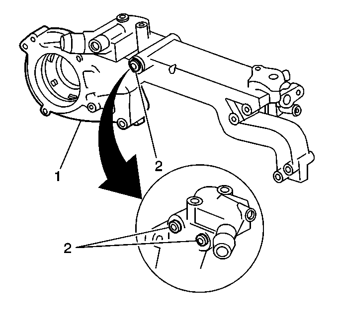
| 4.1. | Remove Crossover Water pump Housing. |
| 4.2. | Remove 2 plugs (2) and clean passages with a wire brush. Remove all loose particles. |
| 4.3. | Put Crossover Water pump Housing back on engine. |
