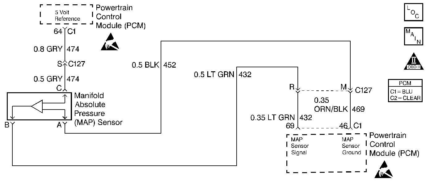
Circuit Description
This diagnostic test monitors Throttle Position (TP) sensor, Engine Speed, Manifold Absolute Pressure (MAP), EGR Flow, and Air Conditioning (A/C) clutch status. Engine operation requires that a large change in manifold pressure must be preceded by a change in engine load due to changes in throttle angle, engine speed, EGR flow or A/C clutch status. If TP sensor, engine speed, EGR Flow, and A/C Clutch remain constant, and there is a rapid change in MAP, DTC P0106 will set.
Conditions for Setting the DTC
Test Conditions
| • | DTCs P0122 and P0123 not set. |
| • | Engine speed 500 RPM or greater. |
Failure Condition
MAP changes by more than 10 kPa in 12.5 milliseconds during a period when engine speed varied less than 4 RPM, throttle angle varied less than 1 degree, EGR fuel compensation varied less than 4%, A/C clutch did not cycle, overheat/low coolant condition was not present, and traction control was not active.
Action Taken When the DTC Sets
| • | PCM turns ON the Service Emission System message. |
| • | PCM uses a substitute MAP value based on engine RPM and throttle angle. |
| • | PCM uses 92.2 kPa for barometric pressure. |
| • | The PCM will illuminate the malfunction indicator lamp (MIL) when the diagnostic runs and fails. |
| • | The PCM will record operating conditions at the time the diagnostic fails. This information will be stored in the Freeze Frame and Failure Records. |
Conditions for Clearing the MIL/DTC
| • | The PCM will turn the MIL OFF after three consecutive drive trips that the diagnostic runs and does not fail. |
| • | A Last Test Failed (current) DTC will clear when the diagnostic runs and does not fail. |
| • | A History DTC will clear after forty consecutive warm-up cycles with no failures of any emission related diagnostic test. |
| • | Use a scan tool to clear DTCs. |
| • | Interrupting PCM battery voltage may or may not clear DTCs. This practice is not recommended. Refer to Clearing Diagnostic Trouble Codes in PCM Description and Operation. |
Diagnostic Aids
Perform the Powertrain Ground Check chart in this section looking for poor or open grounds which could cause an intermittent signal problem.
Test Description
Number(s) below refer to the step number(s) on the Diagnostic Table.
-
Since a misfire can cause DTC P0106 to set, if a misfire has occurred, it should be diagnosed first.
-
Checking if the MAP sensor can read barometric pressure correctly (85 to 105 kPa). An accurate Indicator of the expected MAP reading for any elevation can be obtained by multiplying the local barometer reading from the weather service by 3.4. This will indicate the approximate MAP (BARO) reading in kPa with the key ON and the engine OFF.
-
Checking the MAP sensor's ability to react to a known vacuum (26 to 34 kPa).
-
Checking the MAP sensor's ability to react to a known vacuum (26 to 34 kPa).
-
Checking the MAP sensor's ability to react to a sudden change in vacuum.
Step | Action | Value(s) | Yes | No |
|---|---|---|---|---|
1 | Was the Powertrain On-Board Diagnostic (OBD) System Check performed? | -- | Go to A Powertrain On Board Diagnostic (OBD) System Check | |
Is DTC P0300 also set? | -- | Go to DTC P0300 Engine Misfire Detected | ||
Is the value displayed greater than the value shown? | 75 kPa @ altitude 95 kPa @ sea level | |||
Was a skip or jump noted? | -- | |||
With 20 inches of vacuum applied to the MAP sensor, is the MAP sensor reading the same or less than the value shown? | 34 kPa | |||
Disconnect vacuum source from MAP sensor. Does MAP sensor reading return to original reading? | -- | Fault not present. Refer to Diagnostic Aids | ||
7 | Replace the MAP sensor. Refer to MAP Sensor Replacement . Is the replacement complete? | -- | Go to Powertrain Control Module Diagnosis for Verify Repair | -- |
