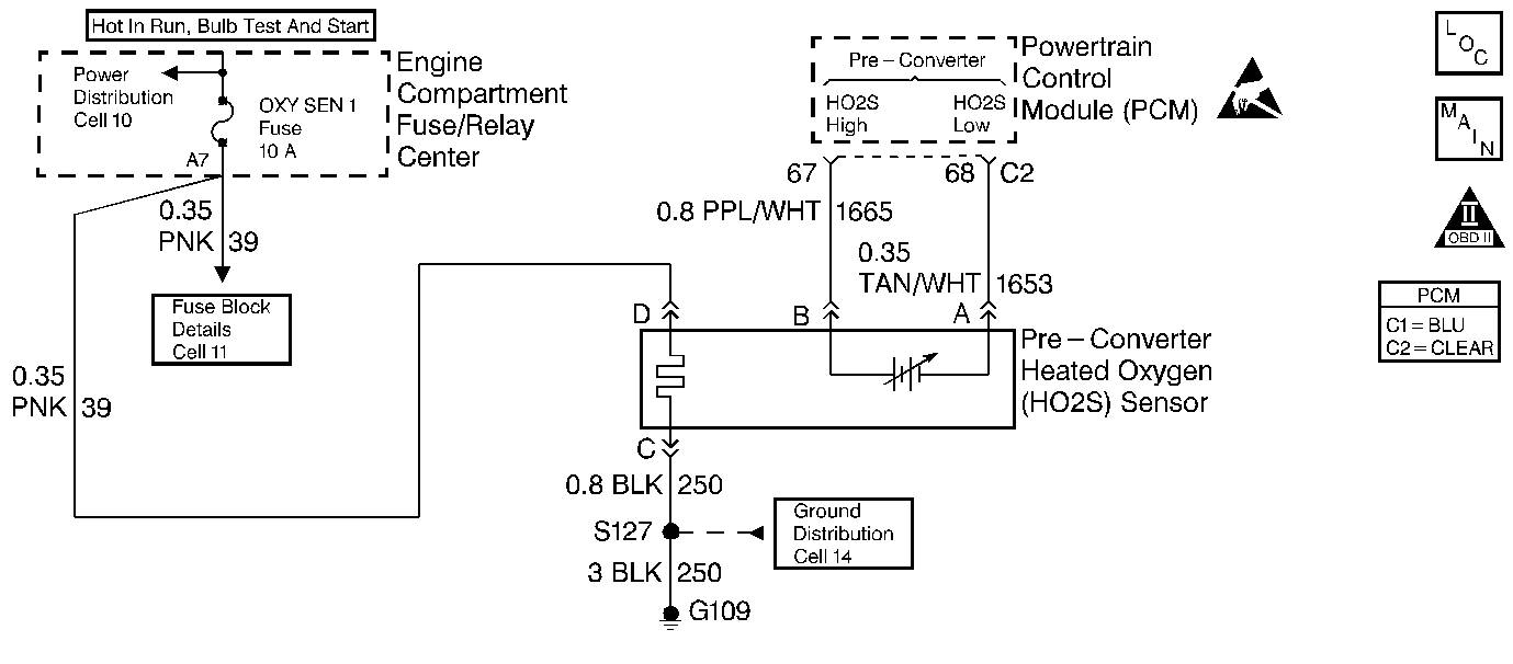
Circuit Description
This diagnostic test monitors catalytic converter efficiency, the ability of the catalytic converter to perform its function in reducing exhaust emissions of hydrocarbons, carbon monoxide, and oxides of nitrogen. This test is only run once per ignition cycle and only after the catalytic converter has warmed up to operating temperature. Catalytic converter efficiency is calculated using data collected from the pre- and post-converter oxygen sensors during steady state driving conditions. In general, the pre-converter oxygen sensor signal should fluctuate like those of the front and rear oxygen sensor. The post-converter oxygen sensor signal should fluctuate less than the pre-converter sensor. The catalytic converter efficiency test is performed in two stages. The first stage calculates post-converter oxygen sensor deviation, difference from the average value, compares these deviations to the maximum allowable deviation, based on air flow, and records a failure if those deviations are excessive. The second stage is only run if the first stage fails or DTC P0420 is currently set. The second stage averages the difference between the deviations calculated in the first stage and the maximum allowable deviations. If the second stage average is too high, DTC P0420 will set.
Conditions for Setting the DTC
Test Conditions
| • | DTC's P0101, P0102, P0103, P0117, P0118, P0122, P0123, P0131, P0132, P0133, P0134, P0135, P0137, P0138, P0139, P0140, P0141, P0143, P0144, P0146, P0147, P0151, P0152, P0153, P0154, P0155, P0171, P0172, P0174, P0175, P0300, P0441, P0502, P1133, P1134, P1139, P1140, P1153, P1154 or P1441 not set. |
| • | DTC P0420 test has not run this ignition cycle. |
| • | Catalytic converter at operating temperature. |
| • | ECT 75°C (167°F) or greater. |
| • | IAT is -28°C (-18°F) or greater. |
| • | Air flow between 15 and 35 grams per second. |
| • | Average MAP signal less than 59.3 kPa. |
| • | Difference between current MAP signal and average MAP signal less than 8 kPa. |
| • | Vehicle speed between 20 and 75 MPH. |
| • | Throttle position greater than 2.2 degrees. |
| • | Engine speed 3000 RPM or less. |
| • | Closed loop fuel control enabled. |
| • | Front and rear oxygen sensors ready. |
| • | Commanded air/fuel ratio 14.7 to 1. |
| • | Short term fuel trim not limited. |
Failure Conditions
| • | Stage 1 average difference between actual oxygen sensor deviation and maximum allowable deviation greater than 93 millivolts. |
| • | Stage 2 average of the average differences calculated in stage 1 is greater than 9 millivolts. |
Action Taken When the DTC Sets
| • | The PCM will illuminate the malfunction indicator lamp (MIL) when the diagnostic runs and fails. |
| • | The PCM will record operating conditions at the time the diagnostic fails. This information will be stored in the Freeze Frame and Failure Records. |
Conditions for Clearing the MIL/DTC
| • | The PCM will turn the MIL OFF after three consecutive drive trips that the diagnostic runs and does not fail. |
| • | A Last Test Failed (current) DTC will clear when the diagnostic runs and does not fail. |
| • | A History DTC will clear after forty consecutive warm-up cycles with no failures of any emission related diagnostic test. |
| • | Use a scan tool to clear DTCs. |
| • | Interrupting PCM battery voltage may or may not clear DTCs. This practice is not recommended. Refer to Clearing Diagnostic Trouble Codes in PCM Description and Operation. |
Diagnostic Aids
Fuel with a high sulfur content can cause a marginal converter to look bad. Check fuel quality.
Test Description
Number(s) below refer to the step number(s) on the Diagnostic Table.
Step | Action | Value(s) | Yes | No |
|---|---|---|---|---|
1 | Was the Powertrain On-Board Diagnostic (OBD) System Check performed? | -- | Go to A Powertrain On Board Diagnostic (OBD) System Check | |
2 |
Are any other DTCs set? | -- | Go to DTCs that are set | |
3 |
Was a repair to the exhaust system made? | -- | ||
4 |
Was a repair made? | -- | ||
5 |
Did this DTC fail? | -- | System OK | |
6 | Replace the catalytic converter. Is the replacement complete? | -- | System OK | -- |
