Information Sensors Description
Engine Coolant Temperature (ECT) sensor
The Engine Coolant Temperature (ECT) sensor is a thermistor (a resistor
which changes value based on temperature) mounted in the engine coolant stream.
Low coolant temperature produces a high resistance (100,000 ohms at -40°C/-40°F),
while high temperature causes low resistance (70 ohms at 130°C/266°F).
The PCM supplies a 5 volt signal to the ECT sensor through a resistor
in the PCM and monitors the terminal voltage. Since this forms a series circuit
to ground through the ECT sensor, high sensor resistance (low temperature)
will result in high PCM terminal voltage. When the ECT sensors resistance
is low (high temperature), the terminal voltage will be drawn lower. This
terminal voltage indicates engine coolant temperature to the PCM.
A hard fault in the ECT sensor circuit should set either a DTC P0117
or P0118. An intermittent failure in the ECT sensor circuit should set either
a P1114 or P1115. Remember, these DTCs indicate a fault in the engine coolant
temperature circuit, so proper use of the DTC table will lead to either repairing
a wiring problem or replacing the sensor, to properly repair a problem.
Heated Oxygen Sensors (HO2S)
Four oxygen sensors are mounted in the exhaust system where they monitor
the oxygen content in the exhaust stream. There is an oxygen sensor mounted
in each exhaust manifold and one on each end of the catalytic converter. The
oxygen sensor located in the front exhaust manifold is the Bank 2 Sensor 1
(Front) sensor. The oxygen sensor located in the rear exhaust manifold is
the Bank 1 Sensor 1 (Rear) sensor. The oxygen sensor located in the Y-pipe
ahead of the catalytic converter is the Bank 1 Sensor 2 (Pre-converter)
sensor. The oxygen sensor located in the catalytic converter outlet is the
Bank 1 Sensor 3 (Post-converter) sensor.
An oxygen sensor acts like a battery because it creates its own signal
voltage once it reaches operating temperature. This voltage is produced when
the oxygen content in the exhaust stream is different than the oxygen content
in the atmosphere. A lean condition (high oxygen content in exhaust) will
produce a low voltage (near 0 volt) and a rich condition (low oxygen content
in exhaust) will produce a high voltage (near one volt). The PCM provides
a reference signal voltage (0.45 volt) and a ground to the sensor. The PCM
reference voltage is necessary because the oxygen sensors do not provide their
own voltage until they reach operating temperature.
The oxygen sensors also incorporate a heating element inside of the
sensor housing. This heating element is energized with the ignition On and
allows the sensors to reach operating temperatures quickly. The PCM can then
use oxygen sensor information sooner after engine startup.
The PCM uses oxygen sensor information during Closed Loop operation
to constantly adjust fuel control to reduce exhaust emissions. Because the
oxygen sensors provide information sooner after engine startup, exhaust emissions
are reduced. Faulty oxygen sensors will cause various driveability conditions
and will set a DTC.
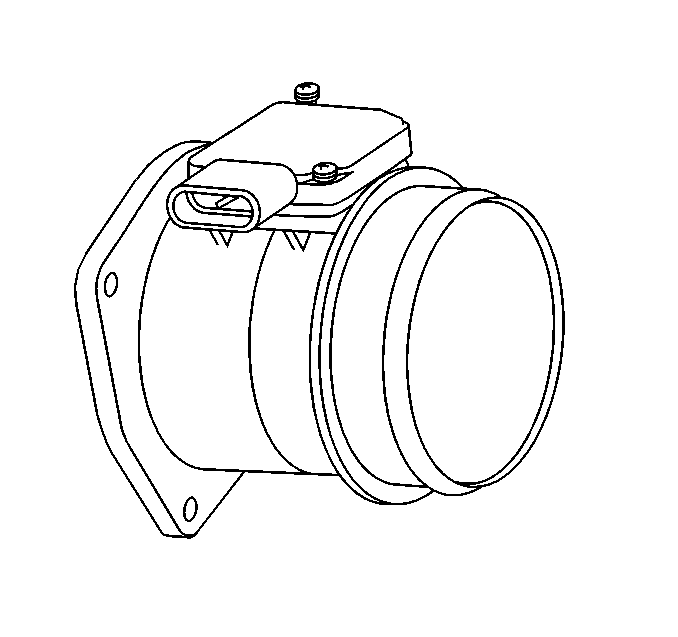
Mass Air Flow (MAF) Sensor

The MAF sensor used on this vehicle is a hot wire type and is used
to measure air flow rate (mass/unit time). The MAF sensor output is a variable
frequency square wave based on air mass traveling through the sensor. A low
frequency output signal from the MAF sensor indicates low air flow and high
frequency indicates high air flow. The MAF sensor has two wires crossing the
air stream through it. One senses ambient temperature and the other, the hot
wire, is kept at a fixed temperature above the ambient temperature. The MAF
sensor senses air flow by measuring the power necessary to keep the hot wire
hot, which is proportional to air flow, and converts it to a frequency modulate
output signal.
The Mass Air Flow (MAF) sensor is located between the intake air duct
and the throttle body. It senses the amount of air entering the intake manifold.
This information is required by the PCM to control fuel and emissions.
Intake Air Temperature (IAT) sensor
The IAT sensor is a thermistor (a resistor which changes value based
on temperature) mounted inside of the air cleaner housing and measures the
air temperature entering the engine. At cold air temperatures, the IAT sensor
resistance is high and at hot air temperatures, the resistance of the sensor
is low. The PCM supplies a 5 volt reference signal and a ground to the sensor
and measures the voltage signal as it is changed by the sensor. The voltage
is close to 5 volts at cold temperatures and close to zero volt at hot temperatures.
Manifold Absolute Pressure (MAP) Sensor

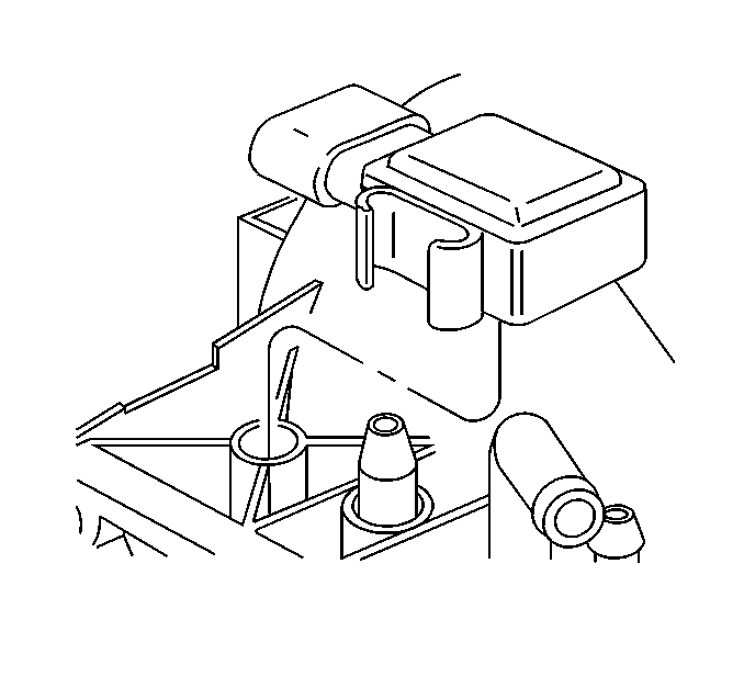
The MAP sensor is mounted on top of the intake manifold and measures
the changes in intake manifold pressure which result from engine speed and
load changes. The PCM supplies a 5 volt reference signal and a ground to the
sensor and the sensor outputs another voltage signal that is proportional
to the pressure signal. A high pressure (low vacuum) will produce a signal
close to 5 volts and a low pressure (high vacuum) will produce a signal under
one volt. The PCM scales the MAP sensor signal in kilo-Pascals (kPa).
The MAP signal is the Inverse of what is read on a vacuum gage. When the MAP
value is high, intake vacuum with a vacuum gage will be low.
The PCM uses MAP information for EGR control and diagnostics. MAP information
is also used to determine barometric pressure and for ignition control. A
faulty MAP sensor may cause various driveability conditions and should set
a DTC.
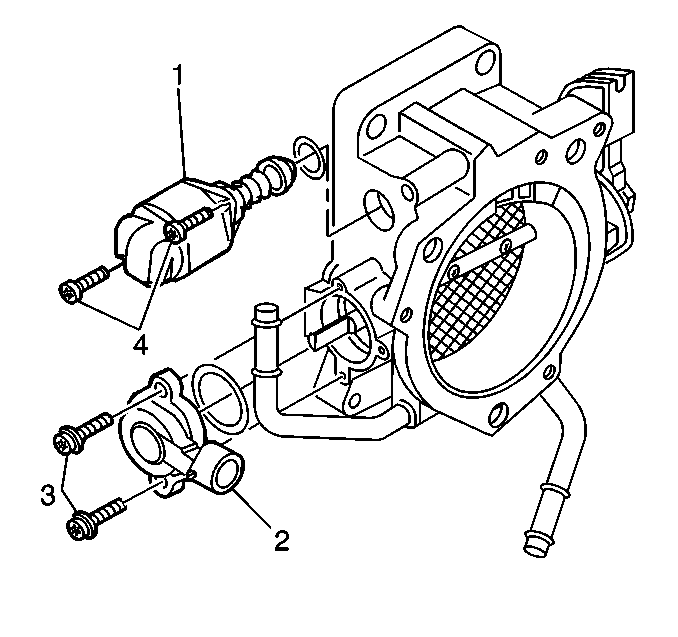
Throttle Position (TP) Sensor


