For 1990-2009 cars only
Front Seat Lumbar Support Replacement AL2
Removal Procedure
Caution: Refer to SIR Caution in the Preface section.
- Disable the SIR system. Refer to Disabling the SIR System in SIR.
- Remove the seat back trim cover. Refer to Front Seat Back Trim Replacement .
- Disconnect the power lumbar assembly electrical connectors (4).
- Disconnect the heated seat connectors.
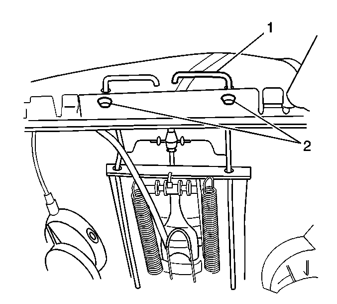
- Remove the upper retainer clips (2) securing the power lumbar assembly (1) to the seat back frame.
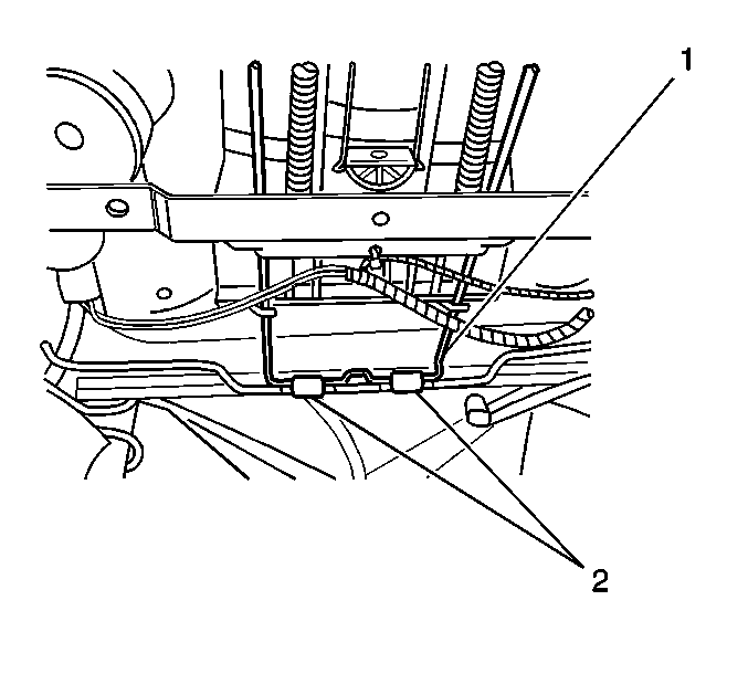
- Remove the lower retainer clips (2) securing the power lumbar assembly (1) to the seat back frame.
- Remove the power lumbar assembly from the seat back frame.
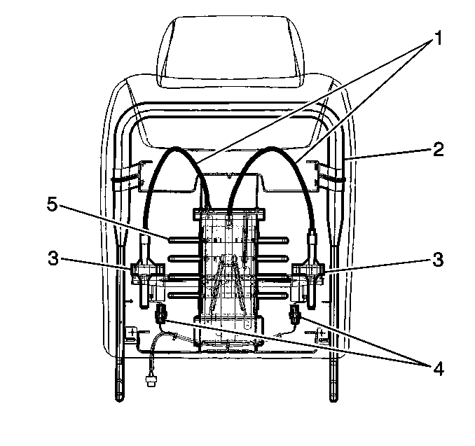
Important: Note the location and position of the power lumbar and heated seat wiring for proper installation location.
Installation Procedure
- Install the power lumbar assembly (1) to the seat back frame.
- Install the lower retainer clips (2) securing the power lumbar assembly (1) to the seat back frame.
- Install the upper retainer clips (2) securing the power lumbar assembly (1) to the seat back frame.
- Route the power lumbar and heated seat electrical connectors through the seat cushion frame.
- Connect the electrical connectors (4).
- Install the seat back trim cover. Refer to Front Seat Back Trim Replacement .
- Verify the operation of the power lumbar support.
- Enable SIR system. Refer to Enabling the SIR System in SIR.
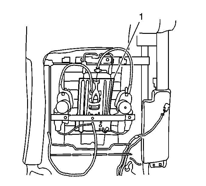


Front Seat Lumbar Support Replacement AM3
Removal Procedure
Caution: Refer to SIR Caution in the Preface section.
- Disable the SIR system. Refer to Disabling the SIR System in SIR.
- Remove the seat back trim. Refer to Front Seat Back Trim Replacement .
- Disconnect the massaging lumbar (1) and the heated seat electrical connectors (1).
- Remove the lower retaining clips (2) securing the massaging lumbar assembly (1) to the seat back frame.
- Remove the upper retaining clips (2) securing the massaging lumbar assembly (1) to the seat back frame.
- Remove the massaging lumbar assembly from the seat back frame.
Important: Note the location and the position of the power lumbar (1) and heated seat wiring for proper installation location.
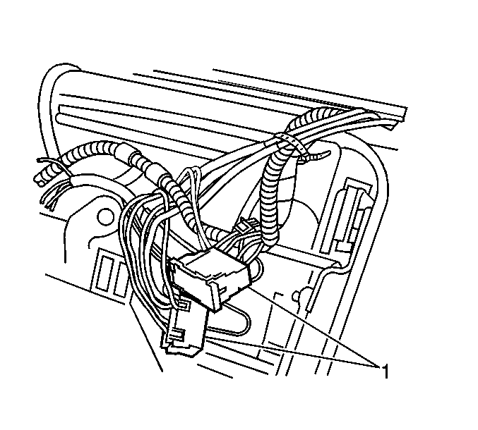


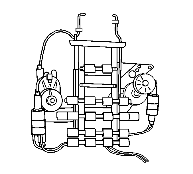
Installation Procedure
- Install the massaging lumbar assembly (1) to the seat back frame.
- Install the lower retaining clips (2) securing the massaging lumbar (1) to the seat back frame.
- Install the upper retaining clips (2) securing the massaging lumbar (1) to the seat back frame.
- Route the massaging lumbar and heated seat electrical connectors (1) through the seat cushion frame.
- Connect the electrical connectors (1).
- Install the seat back trim cover. Refer to Front Seat Back Cushion Cover and Cushion Pad Replacement .
- Ensure the massaging lumbar operates properly.
- Enable SIR system. Refer to Enabling the SIR System in SIR.


Front Seat Lumbar Support Replacement AC9
Removal Procedure
Caution: Refer to SIR Caution in the Preface section.
- Disable the SIR system. Refer to Disabling the SIR System in SIR.
- Adjust the front seat forward and up.
- Remove the seat back trim cover. Refer to Front Seat Back Trim Replacement .
- Remove the seat cover J channels from the seat frame, as necessary, in order to access the adaptive lumbar module and pump motor wiring.
- Disconnect the air line connections from the adaptive lumbar module.
- Disconnect the electrical connectors from the adaptive lumbar module.
- Disconnect the electrical connector and single air line from the adaptive lumbar pump motor.
- Remove the hook and loop material that retains the adaptive lumbar module and the adaptive lumbar pump motor to the seat back frame.
- Remove the adaptive lumbar pump motor from the seat back frame.
- Remove the adaptive lumbar module from the seat back frame.
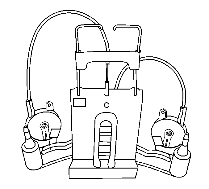
Important: The adaptive lumbar module (2) and pump motor (1) are serviced as an assembly.
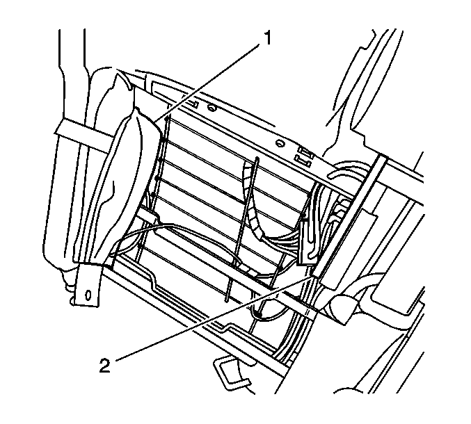
Important: Note the routing of the electrical wiring and the air lines for the lumbar in order to ensure proper routing during reassembly.
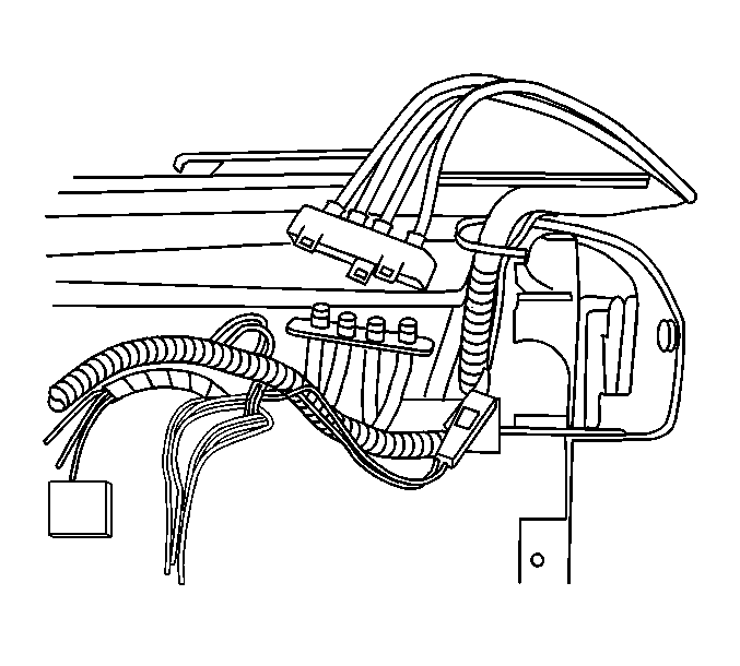
Installation Procedure
- Install the adaptive lumbar module (2) and the pump motor to the seat back frame.
- Secure the adaptive lumbar module (2) and the pump motor (1) to the seat back frame with hook and loop material.
- Reconnect the air line connections to the adaptive lumbar module and the pump motor.
- Reconnect the electrical connections to the adaptive lumbar module and the pump motor.
- Install the seat back J channels to the seat back frame.
- Operate the recliner assembly forward and back in order to ensure that there is not interference with the module wiring and the air line connections.
- Install the seat back trim cover. Refer to Front Seat Back Trim Replacement .
- Enable SIR system. Refer to Enabling the SIR System in SIR.


