Customer Satisfaction-Driver Door Lock Cylinder and Engine Wire Harness Chafing

| Subject: | 03016 - Driver Door Lock Cylinder and Engine Wire Harness Chafing |
| Models: | 2002-2003 Cadillac DeVille |
Condition
General Motors has decided that certain 2002 and 2003 model year Cadillac DeVille vehicles may have a driver door lock cylinder that may not perform as intended, which may create a security risk for personal articles left in the car.
In addition, certain 2003 model year vehicles may have a condition in which a hose clamp could come in contact with the engine harness. If the hose clamp wears through the insulation and contacts more than one of the wires in the engine harness, it could result in the illumination of the Service Engine Soon/Check Engine Light, Anti-Lock Brakes (ABS) Warning Light, loss of cruise control, erratic speedometer reading, and/or erratic transmission shifting within the selected gear.
Correction
Dealers are to replace the driver door lock cylinder on all vehicles, and on certain 2003 model year vehicles, reposition the hose clamp and repair the engine harness wiring if it is damaged.
Vehicles Involved
Involved are certain 2002-2003 Cadillac DeVille vehicles built within these VIN breakpoints:
Year | Division | Model | From | Through |
|---|---|---|---|---|
2002 | Cadillac | DeVille | 2U220600 | 2U306394 |
Hearse | 2U500675 | 2U501039 | ||
Limo | 2U550663 | 2U550971 | ||
2003 | Cadillac | DeVille | 3U100001 | 3U228230 |
Hearse | 3U500001 | 3U500547 | ||
Limo | 3U550001 | 3U550425 |
Important: Dealers should confirm vehicle eligibility through GMVIS (GM Vehicle Inquiry System) or GM Access Screen (Canada only) or DCS Screen 445 (IPC only) prior to beginning program repairs. [Not all vehicles within the above breakpoints may be involved.]
Involved vehicles have been identified by Vehicle Identification Number. Computer listings containing the complete Vehicle Identification Number, customer name and address data have been prepared, and are being furnished to involved dealers with the program bulletin. The customer name and address data furnished will enable dealers to follow up with customers involved in this program. Any dealer not receiving a computer listing with the program bulletin has no involved vehicles currently assigned.
These dealer listings may contain customer names and addresses obtained from Motor Vehicle Registration Records. The use of such motor vehicle registration data for any other purpose is a violation of law in several states/provinces/countries. Accordingly, you are urged to limit the use of this listing to the follow-up necessary to complete this program.
Parts Information
Parts Pre-Ship Information - For US and Canada
Important: An initial supply of parts required to complete this program will be pre-shipped to involved dealers of record. This pre-shipment is scheduled to begin the week of June 9, 2003. Pre-shipped parts will be charged to dealer's open parts account.
Parts required to complete this program are to be obtained from General Motors Service Parts Operations (GMSPO). Please refer to your "involved vehicles listing" before ordering requirements. Normal orders should be placed on a DRO = Daily Replenishment Order. In an emergency situation, parts should be ordered on a CSO = Customer Special Order.
Part Number | Description | Qty/ Vehicle |
|---|---|---|
89022356 | Cylinder Kit, Frt S/D Lk | 1 |
Service Procedure
The following service procedure provides instructions for replacing the driver's door lock cylinder and also for inspection/repositioning of a hose clamp in the engine compartment. Please note that all 2002 and 2003 model year vehicles require the replacement of the driver's door lock cylinder. Repositioning of the hose clamp is only required on certain 2003 models that fall within the VIN breakpoints supplied in the service procedure.
The service procedure contained in this program is different from the service procedure found in the appropriate Service Manual. As a result, the labor time allowance has been revised to correspond with this new service procedure. In the near future the Service Manual and labor time guide will be updated with this new information.
- Place the driver's door glass in the full up position.
- Verify that the manual lock knob/button is in the unlock position.
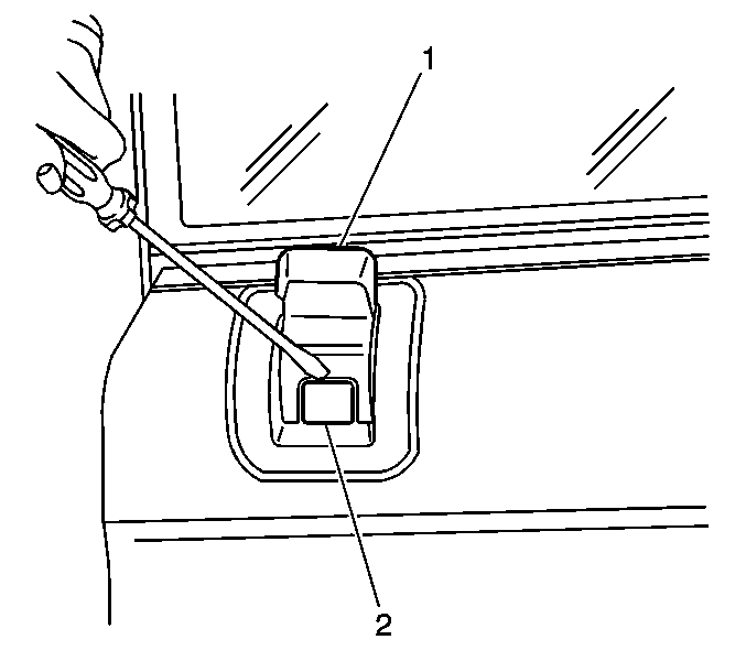
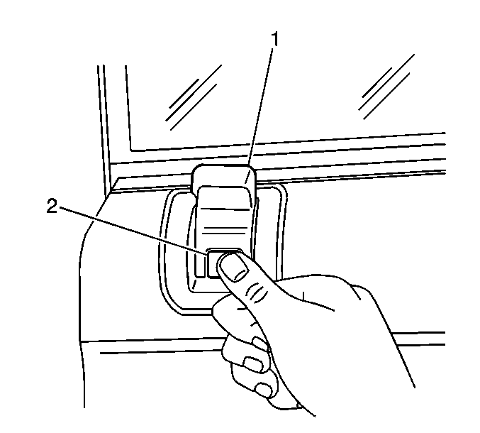
- Insert a flat bladed tool into the top service notch in order to disengage the locking clip (2) located at the front of the manual lock knob (1).
- Remove the manual lock knob/button (1).
- Remove the inside door handle bezel from the inner door panel in the following order:
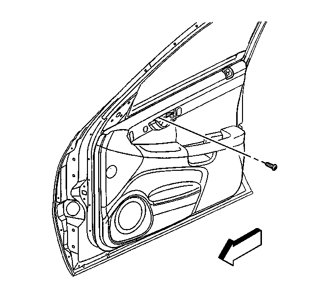
- Remove the screw attaching the inside door handle to the sheet metal.
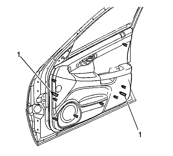
- Use J 36796 or J 38778 in order to release the retainers (1) around the outside edges of the door trim panel.
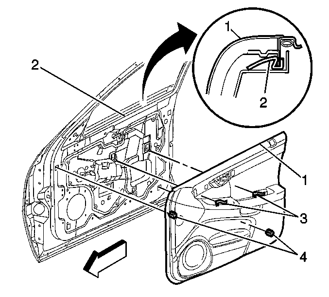
- Slide the door trim panel (1) upwards to release it from the following:
- Disconnect the door trim panel electrical connector.
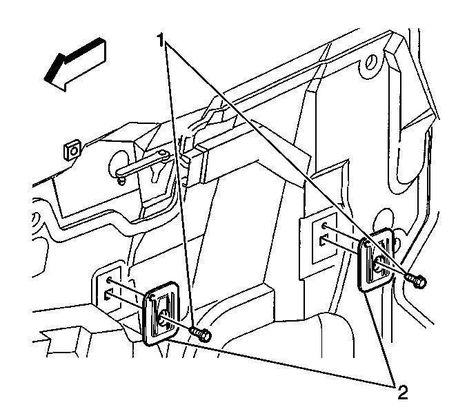
- Remove the two fasteners (1) attaching the nylon nuts (2) to the inner panel.
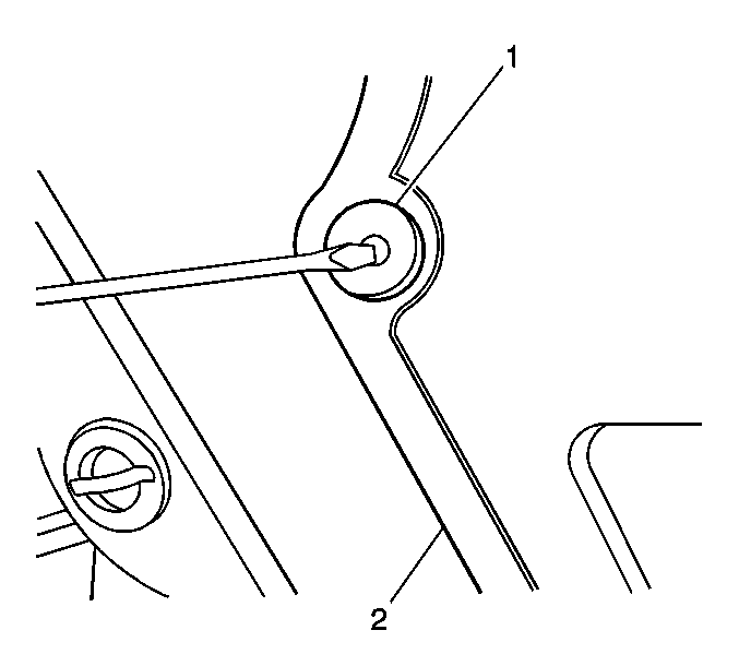
- Press the center stud of the retainers (1) inwards in order to remove the water deflector (2).
- Pull the water deflector away from the door panel and reposition it away from the rearward end of the door assembly.
- Disconnect the door lock cylinder switch electrical connector for the harness in the door.
- Disconnect the lock rod from the pawl on the end of the lock cylinder.
- Insert a flat bladed tool (1) between the bottom of the door lock cylinder opening in the door handle and the retaining spring clip (2).
- Using your right hand, twist the flat bladed tool clockwise to release the spring clip.
- While holding the flat bladed tool in the rotated position with your right hand, use your left hand to push the door lock cylinder out of the door handle from the other side (outside) of the door.
- Once the lock cylinder is out of the handle, release the flat bladed tool and allow the retaining spring clip to return to its original position on the door handle.
- Remove the lock cylinder and switch assembly from the door.
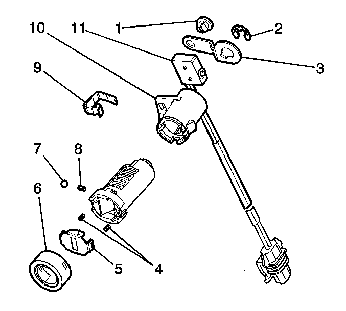
- Remove the two small screws attaching the switch (11) to the lock cylinder housing (10).
- Remove the cap (6), shutter (5), and two springs (4) from the lock cylinder assembly.
- Remove the retaining ring (2) attaching the pawl (3) to the end of the lock cylinder, and remove the pawl.
- Insert the key into the lock cylinder.
- Carefully remove the cylinder (6) from the housing.
- Remove the key and place the cylinder on a clean work surface.
- Take the new cylinder from the kit and place it next to the original cylinder.
- Transfer one tumbler and spring at a time from the original cylinder to the new cylinder.
- After all the tumblers and springs have been transferred, press all of them inwards in the new cylinder and hold while inserting the key.
- Install the new spring (8) and then the ball bearing (7) into the hole in the side of the new cylinder.
- Depress the ball and spring, and insert the cylinder into the new housing (10).
- With the key still inserted into the lock cylinder, install the pawl (3) and retaining ring (2) on the end of the cylinder.
- Verify that the key and cylinder can be rotated in the cylinder and that the key can be removed. Repeat several times.
- With the key removed, install the two small springs (4) and shutter (5) to the assembly and snap the cap (6) into place.
- Reinstall the key and rotate the cylinder as necessary to allow for installation of the switch and screws in the next step.
- Position the switch (11) to the housing (10) and install the two NEW screws included in the kit. Tighten the screws securely.
- Remove the key.
- Position the lock cylinder and switch assembly in the door and route the wiring harness as noted prior to removal.
- Position the lock cylinder in the opening in the door handle and press into place to engage the retaining clip.
- Connect the switch electrical connector to the door wiring harness.
- Connect the lock rod to the pawl on the lock cylinder.
- Insert the key and verify that the lock cylinder operates correctly.
- Reset the retainers for the water deflector by pushing the stud from the backside.
- Install the water deflector to the door assembly in the following order:
- Install the two nylon nuts (2) to the inner panel and install the attaching screws.
- Slide the electrical connector (4) into position on the water deflector (1).
- Remove the two steel retainer clips from the armrest pull handle brackets and install them (2) on the two nylon nuts (3).
- Position the door trim panel (1) to the inner door and move downward over the following:
- Engage the door trim panel simultaneously into the following:
- Install the screw attaching the inside door handle to the sheet metal.
- Install the inside handle bezel to the inner door panel in the following order:
- Position the manual lock knob (1) into the bezel opening until the locking clip (2) bottoms out on the bezel.
- Engage the locking clip (2) located at the front knob (1) to the lock end.
- Lower the driver's door glass. Close all doors and using the key fob transmitter, lock all doors.
- Insert the key in the driver's door lock cylinder, turn clockwise as far as possible, and hold for two seconds to verify that the Central Unlocking System operates correctly (all doors unlock).
- Review the following to determine if any additional repairs are required.
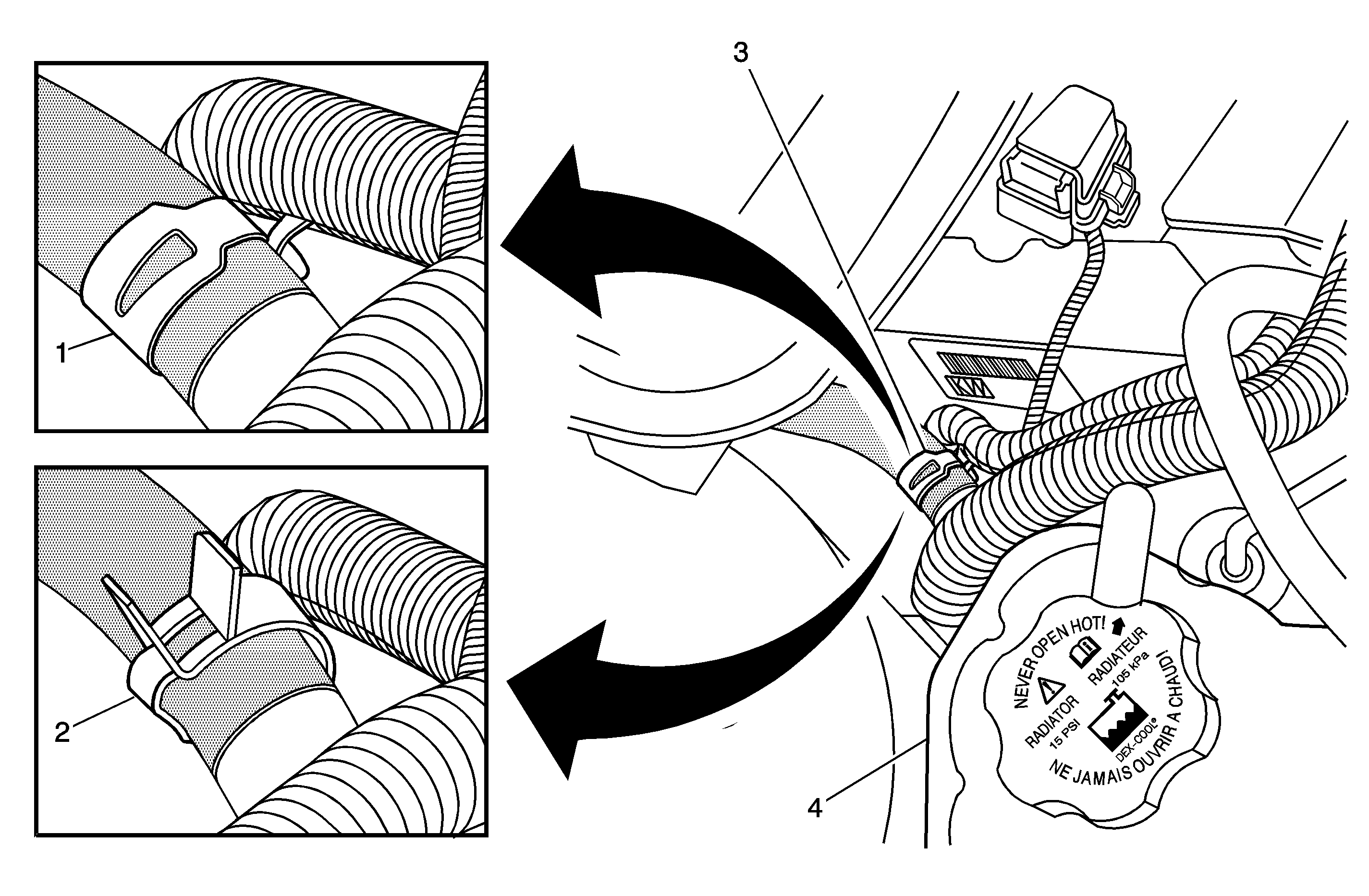
- Open the hood and inspect the clamp (3) on the hose that attaches to the bottom of the radiator surge tank (4).
- If the tang or metal tab on the hose clamp is positioned away from the plastic conduit (2) on the engine wiring harness as shown, the clamp does NOT require repositioning.
- If the tang or metal tab on the hose clamp IS contacting the plastic conduit (1) on the engine wiring harness as shown, the clamp must be repositioned as shown. After repositioning the clamp, open the slit in the plastic conduit and inspect the wires inside for damage. Repair any damaged wires as necessary. Refer to the appropriate section of the Service Manual for wiring repair information. Please note that Area Service Manager (ASM) approval is required if wiring repairs are needed.
- Install the GM Identification Label.
| 5.1. | Hold the inside door handle to the open position. |
| 5.2. | Insert a flat bladed tool at the front lower corner of the bezel. |
| 5.3. | Pry outward on the bezel. |
| 5.4. | Remove the bezel from the inner door panel. |
| • | alignment points (4) |
| • | retainers |
| • | armrest steel retainer clips (3) |
| • | inner belt molding (2) |
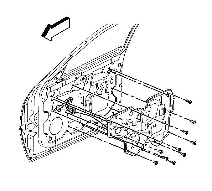
Important: Do not disconnect the electrical connectors or remove the door control module from the water deflector when repositioning the deflector in the next step.
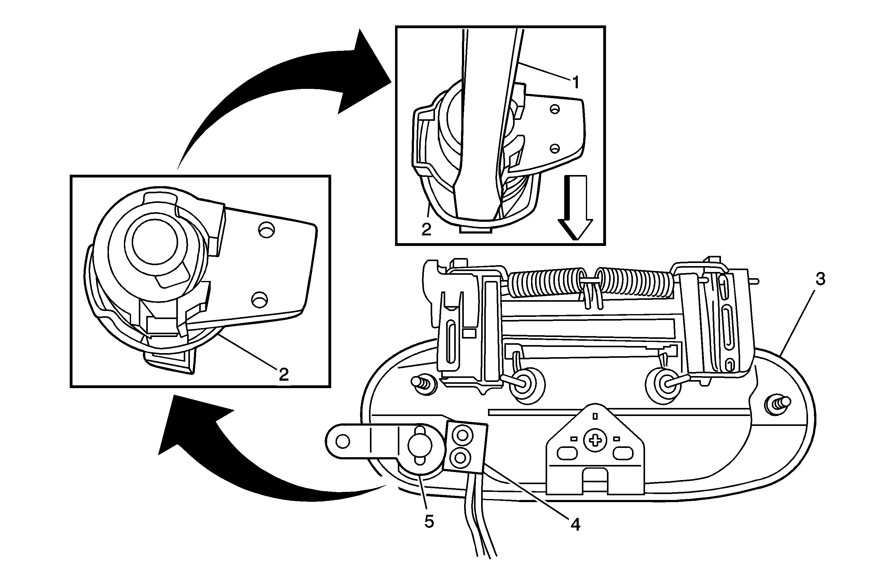
Important: For viewing purposes, the lock cylinder is shown in the close-up views with the pawl (5) and switch (4) removed. Do not remove the pawl or switch from the lock cylinder in order to remove the lock from the door handle (3).
Important: Note the routing of the lock cylinder switch wiring harness before removing in the next step.
Important: If the key is on a key ring with a number of other keys, it is recommended that it be removed from the key ring prior to beginning the recoding of the new lock cylinder. Removing the key will make handling of the key, cylinder, and tumblers easier.
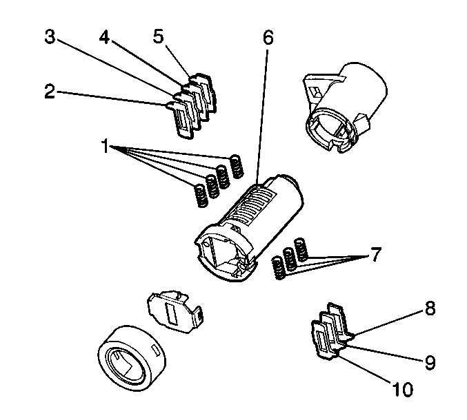
Important: When removing the cylinder from the housing in the next step, a small spring (8) and ball bearing (7) will come out of the side of the cylinder. The replacement lock cylinder kit includes a new ball bearing and spring.
Important: Do not allow the tumblers (2, 3, 4, 5, 8, 9, 10) and spring (1, 7) to fall out of the cylinder (6) when removing it from the housing in the next step.
Important: Apply a small amount of the lubricant included in the kit to the tumbler slots in the new cylinder and inside the opening in the new housing.

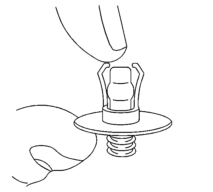

| 43.1. | Align the water deflector to the inner panel. |
| 43.2. | Insert the retainers and press the center stud flush, locking it in place. |

Tighten
Tighten to 2 N·m (18 lb in).
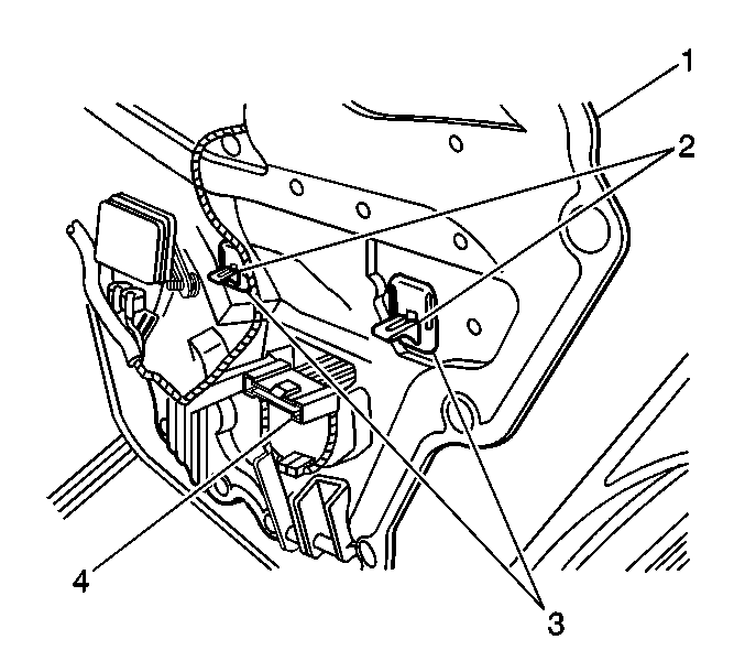

| • | manual lock rod |
| • | inner belt molding (2) |
| • | alignment points (4) |
| • | electrical connector |
| • | armrest pull handle retainer clips (3) |
| • | eight retainers |

Tighten
Tighten to 0.5 N·m (0.4 lb in).
| 50.1. | Hold the inside handle to the open position. |
| 50.2. | Insert the rear hook on the bezel to the wood trim tab. |
| 50.3. | Press the forward end of the bezel inward until it is fully seated. |
Important: Ensure that the manual lock rod is in the full up/unlocked position in the next step.
| • | If the vehicle is a 2002 model year vehicle, no further repairs are required. Install the GM Identification Label. |
| • | If the vehicle is a 2003 model year vehicle and is NOT within the breakpoints listed below, no further repairs are required. Install the GM Identification Label. |
| • | If the vehicle is a 2003 model year vehicle and IS within the breakpoints listed below, proceed to the next step and inspect the hose clamp in the engine compartment. |
| - | 2003 DeVille - From 3U128172 Through 3U222304 |
| - | 2003 Hearse - From 3U500077 Through 3U500512 |
| - | 2003 Limo - From 3U550061 Through 3U550403 |
Identification Label
For US and IPC
Place a Recall Identification Label on each vehicle corrected in accordance with the instructions outlined in this Product Recall Bulletin. Each label provides a space to include the recall number and the five (5) digit dealer code of the dealer performing the recall service. This information may be inserted with a typewriter or a ball point pen.
Put the Recall Identification Label on a clean and dry surface of the radiator core support in an area that will be visible to people servicing the vehicle. When installing the Recall Identification Label, be sure to pull the tab to allow the adhesion of the clear protective covering. Additional Recall Identification Labels for US dealers can be obtained from Dealer Support Materials by either ordering on the web from DWD Store, gm-dealerworld.com, or calling 1-866-700-0001 (Monday-Friday, 8:00 am to 5:00 pm EST). Ask for Item Number S-1015 when ordering.
Additional Recall Identification Labels for IPC dealers can be obtained from your Regional Marketing Office.
Identification Label
For Canada
Place a Recall Identification Label on each vehicle corrected in accordance with the instructions outlined in this Product Recall Bulletin. Each label provides a space to include the recall number and the five (5) digit dealer code of the dealer performing the recall service. This information may be inserted with a typewriter or a ball point pen. Put the Recall Identification Label on a clean and dry surface of the radiator core support in an area that will be visible to people servicing the vehicle. Additional Recall Identification Labels for Canadian dealers can be obtained from DGN by calling 1-800-668-5539 (Monday-Friday, 8:00 a.m. to 5:00 p.m. EST). Ask for Item Number GMP 91 when ordering.
Courtesy Transportation
The General Motors Courtesy Transportation program is intended to minimize customer inconvenience when a vehicle requires a repair that is covered by the New Vehicle Limited Warranty. The availability of courtesy transportation to customers whose vehicles are within the warranty coverage period and involved in a product recall is very important in maintaining customer satisfaction. Dealers are to ensure that these customers understand that shuttle service or some other form of courtesy transportation is available and will be provided at no charge. Dealers should refer to the General Motors Service Policies and Procedures Manual for Courtesy Transportation guidelines.
Claim Information
Submit a Product Program Claim with the information indicated below.
Repair Performed | Part Count | Part No. | Parts Allow | CC-FC | Labor Op | Labor Hours* |
|---|---|---|---|---|---|---|
Install new Door Lock Cylinder (Inc. Coding of New Lock) & Reposition Hose Clamp, If Required**** | 1 | -- | ** | MA-96 | V1006 | 0.7 |
Courtesy Transportation | N/A | N/A | N/A | MA-96 | *** | N/A |
* -- For Program Administrative Allowance, add 0.1 hours to the "Labor Hours". ** -- The "Parts Allowance" should be the sum total of the current GMSPO Dealer Net price plus applicable Mark-Up or Landed Cost Mark-Up (for IPC) for the cylinder kit needed to complete the repair. *** - Submit courtesy transportation using normal labor operations for courtesy transportation as indicated in the GM Service Policies and Procedures Manual. **** - Only certain 2003 model year vehicles will require the hose clamp repositioning (see the service procedure to determine eligibility). If wire repairs are needed, add the additional labor hours to V1006 and route the claim to your Area Service Manager (AVM) for approval. | ||||||
Refer to the General Motors WINS Claim Processing Manual for details on Product Recall Claim Submission.
Customer Notification
For US and Canada
Customers will be notified of this program on their vehicles by General Motors (see copy of customer letter included with this bulletin).
Customer Notification
For IPC
Letters will be sent to known owners of record located within areas covered by the US National Traffic and Motor Vehicle Safety Act. For owners outside these areas, dealers should notify customers using the attached suggested dealer letter.
Dealer Program Responsibility
All unsold new vehicles in dealers' possession and subject to this program MUST be held and inspected/repaired per the service procedure of this program bulletin BEFORE customers take possession of these vehicles.
Dealers are to service all vehicles subject to this program at no charge to customers, regardless of mileage, age of vehicle, or ownership, from this time forward.
Customers who have recently purchased vehicles sold from your vehicle inventory, and for which there is no customer information indicated on the dealer listing, are to be contacted by the dealer. Arrangements are to be made to make the required correction according to the instructions contained in this bulletin. This could be done by mailing to such customers a copy of the customer letter accompanying this bulletin. Program follow-up cards should not be used for this purpose, since the customer may not as yet have received the notification letter.
In summary, whenever a vehicle subject to this program enters your vehicle inventory, or is in your dealership for service in the future, you must take the steps necessary to be sure the program correction has been made before selling or releasing the vehicle.
June, 2003Dear Cadillac Customer:
This notice is sent to inform you that Cadillac is conducting a voluntary customer satisfaction program that affects certain 2002 and 2003 model year DeVille vehicles.
We have learned that your vehicle may have a driver door lock cylinder that may not perform as intended, which may create a security risk for personal articles left in the car.
In addition, certain 2003 model year vehicles may have a condition in which a hose clamp could come in contact with the engine harness. If the hose clamp wears through the insulation and contacts more than one of the wires in the engine harness, it could result in the illumination of the Service Engine Soon/Check Engine Light, Anti-Lock Brakes (ABS) Warning Light, loss of cruise control, erratic speedometer reading, and/or erratic transmission shifting within the selected gear.
What We Have Done
To prevent this from occurring, your Cadillac dealer will replace the driver door lock cylinder, and on certain 2003 model year vehicles, reposition the hose clamp and repair the engine harness wiring if it is damage. This service will be performed for you at no charge .
What You Should Do
We recommend that you contact your Cadillac dealer to arrange a service date.
Presenting the attached card to your dealer will assist in making the necessary correction in the shortest possible time.
If you no longer own this vehicle, please check the appropriate box and provide new owner information, if available.
If you have any questions or need any assistance, just contact your dealer or the appropriate Customer Assistance Center at the number listed below:
Division | Number | Deaf, Hearing Impaired, or Speech Impaired* |
|---|---|---|
Cadillac | 1-800-458-8006 | 1-800-833-2622 |
Puerto Rico - English | 1-800-496-9992 |
|
Puerto Rico - Español | 1-800-496-9993 |
|
Virgin Islands | 1-800-496-9994 |
|
* Utilizes Telecommunication Devices for the Deaf/Text Telephones (TDD/TTY) | ||
If your vehicle is within the New Vehicle Limited Warranty your dealer may provide you with shuttle service or some other form of courtesy transportation while your vehicle is at the dealership for this repair. Please refer to your Owner's Manual and your dealer for details on Courtesy Transportation.
We sincerely regret any inconvenience or concern this situation may cause you. We want you to know that we will do our best, throughout your ownership experience, to ensure that your Cadillac DeVille provides you many miles of enjoyable driving.
Cadillac Motor Car Division
General Motors Corporation
Enclosure
