GM Service Manual Online
For 1990-2009 cars only
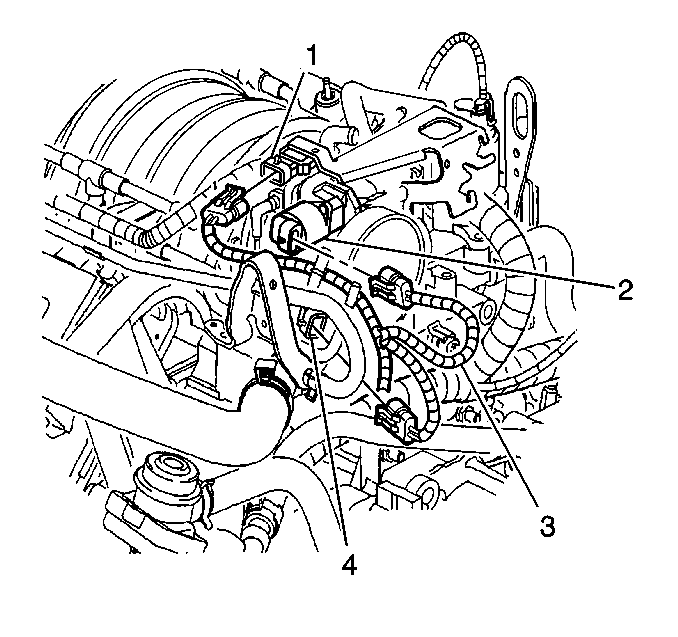
Figure 1:

MAP, IAC, ECT, TP Sensors


Object Number: 602335  Size: SH
(1)Manifold Absolute Pressure (MAP) Sensor
(2)Idle Air Control (IAC) Valve
(3)Engine Coolant Temperature (ECT) Sensor
(4)Throttle Position (TP) Sensor
Figure 2:

Left Side of Engine Compartment


Object Number: 602337  Size: SH
(1)Mass Air Flow (MAF) Sensor
Figure 3:

Rear of Engine Compartment, on the Top Rear of the Engine
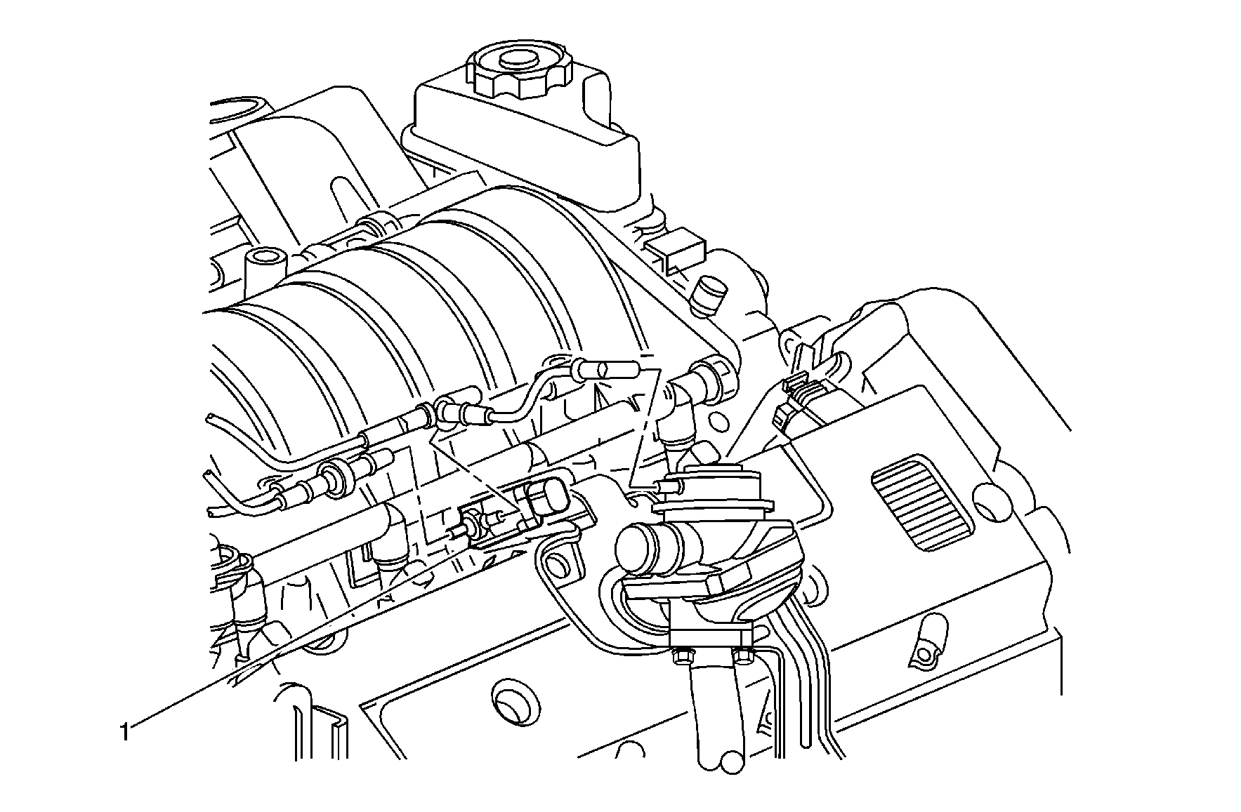

Object Number: 893836  Size: MF
(1)Secondary Air Injection (AIR) Check Valve (NU6)
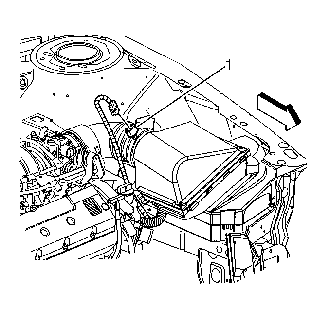
Figure 4:

Left Front Corner of the Engine Compartment
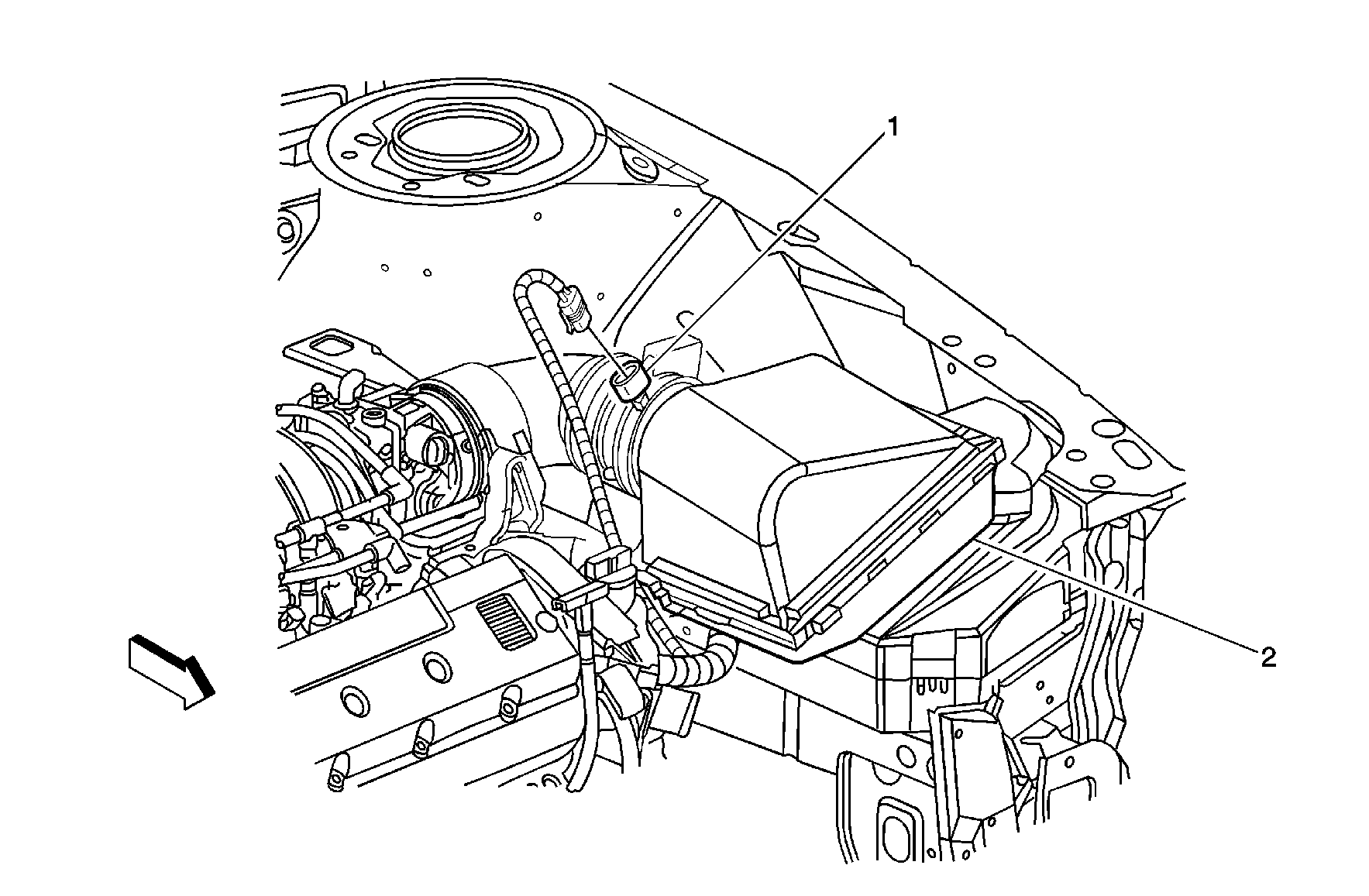

Object Number: 893598  Size: MF
(1)Mass Air Flow (MAF) / Intake Air Temperature (IAT) Sensor
(2)Engine Control Module (ECM), in the Air Cleaner Assembly
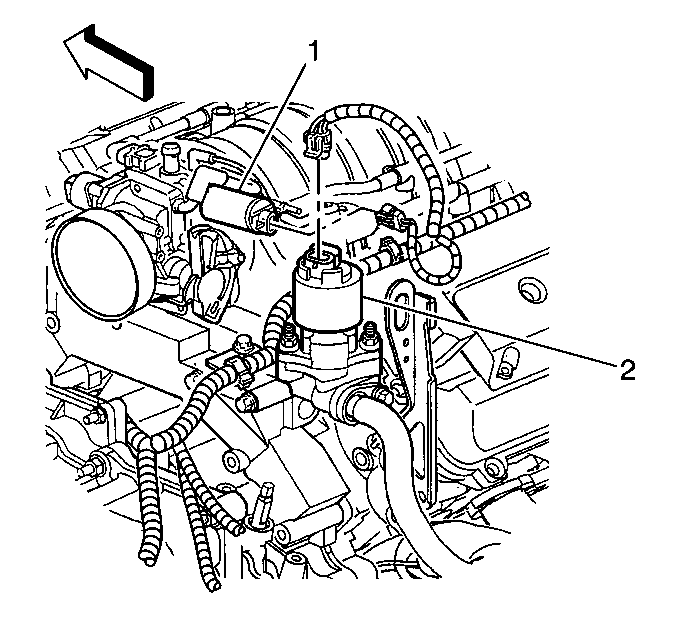
Figure 5:

EVAP Purge Solenoid, and EGR Valve


Object Number: 602336  Size: SH
(1)Evaporative Emission (EVAP) Canister Purge Solenoid Valve
(2)Exhaust Gas Recirculation (EGR) Valve
Figure 6:

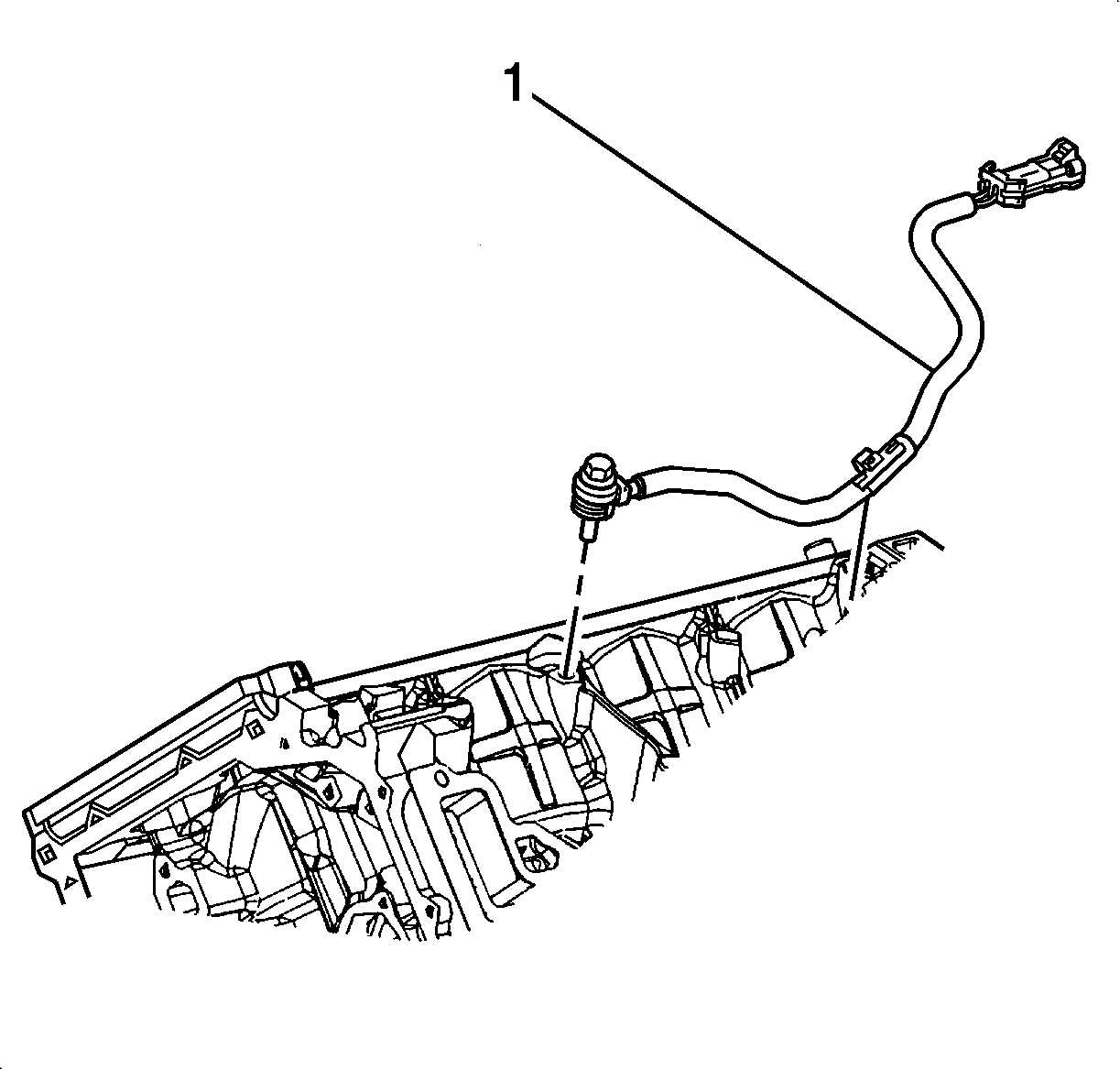
CKP B, CKP A, Engine Oil Pressure Switch, and Engine Oil Level Switch
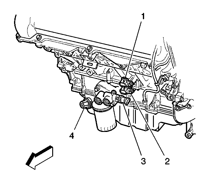

Object Number: 602338  Size: SH
(1)Crankshaft Position (CKP) Sensor B
(2)Crankshaft Position (CKP) Sensor A
(3)Engine Oil Pressure (EOP) Switch
(4)Engine Oil Level Switch
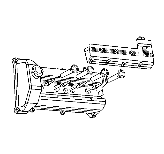
Figure 7:

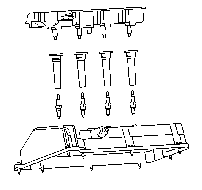
Front Ignition Coil Cassette


Object Number: 602330  Size: SH
Figure 8:

Rear Ignition Coil Cassette


Object Number: 602329  Size: SH
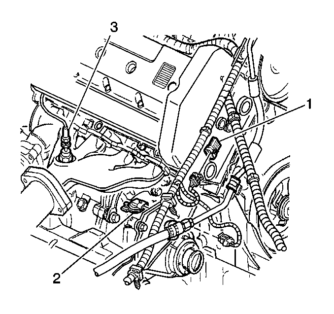
Figure 9:

CMP, VSS, and HO2S Bank 1 Sensor 1


Object Number: 602339  Size: SH
(1)Camshaft Position (CMP) Sensor
(2)Vehicle Speed Sensor (VSS)
(3)Heated Oxygen Sensor (HO2S) Bank 1 Sensor 1
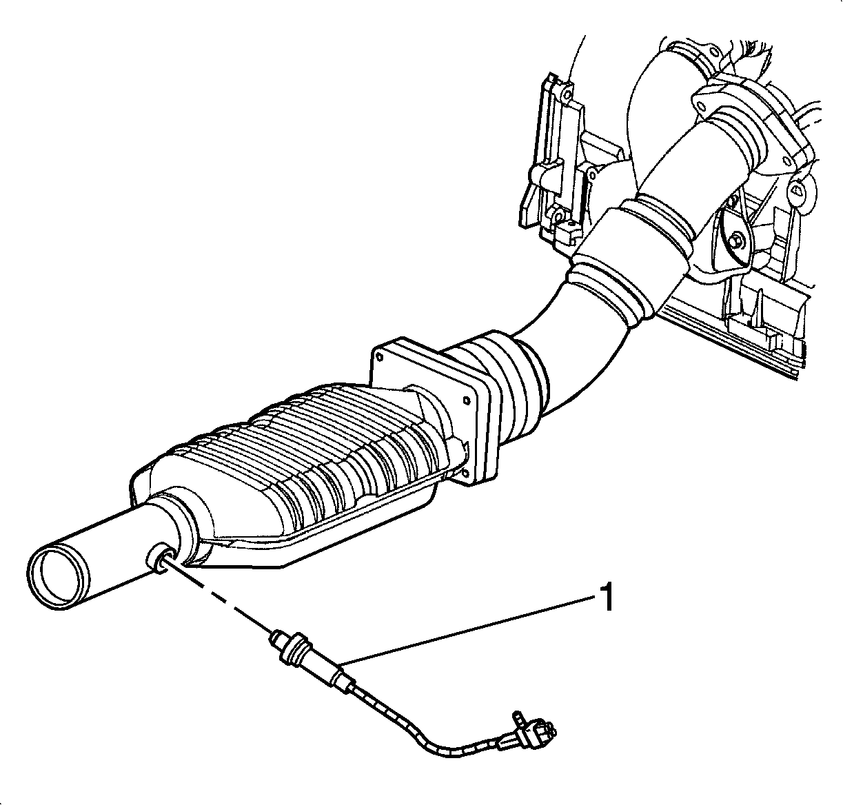
Figure 10:

HO2S Bank 1 Sensor 2 (Post HO2)


Object Number: 1436994  Size: SH
(1)HO2S Bank 1 Sensor 2 (Post HO2)
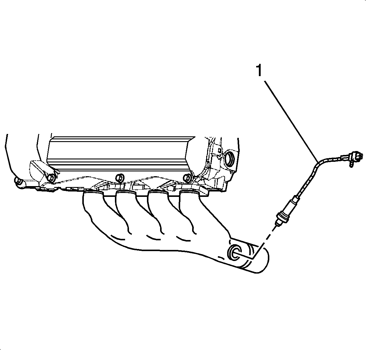
Figure 11:

HO2S Bank 2 Sensor 1 (Front HO2)


Object Number: 1437000  Size: SH
(1)HO2S Bank 2 Sensor 1 (Front HO2)
Figure 12:

Knock Sensors


Object Number: 1436991  Size: SH
(1)Knock Sensor 1 (Knock Sensor 2 Similar)
Figure 13:

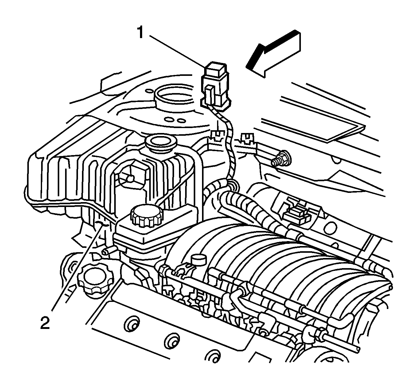
AIR Relay


Object Number: 736519  Size: SH
(1)Secondary Air Injection (AIR) Pump Relay
(2)Coolant Level Switch (in Coolant Surge Tank)
Figure 14:

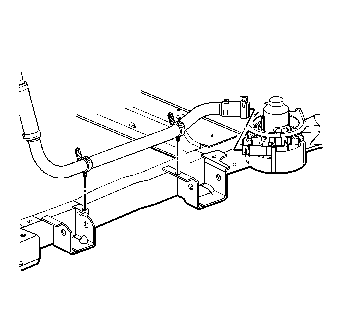
Right AIR Exhaust Hose


Object Number: 602317  Size: SH
Figure 15:

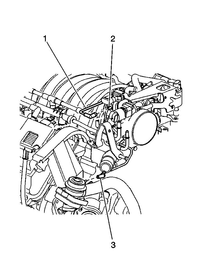
AIR Vacuum Routing


Object Number: 602313  Size: MH
(1)AIR Vacuum Source Hose
(2)AIR Vacuum Source Connection
(3)Control Vacuum to the Front AIR Check Valve
Figure 16:

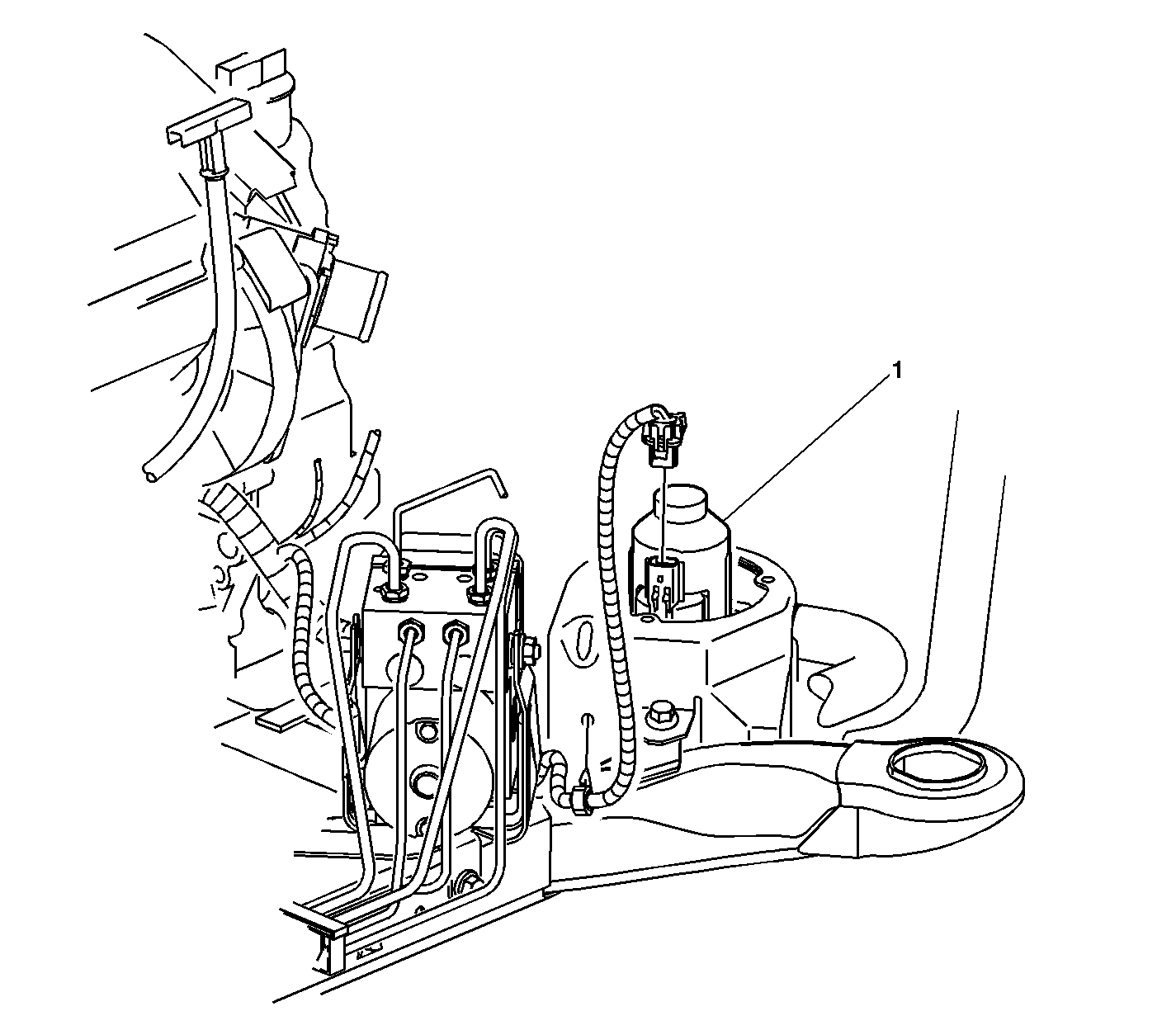
Left Front of the Engine Compartment, on the Frame Rail
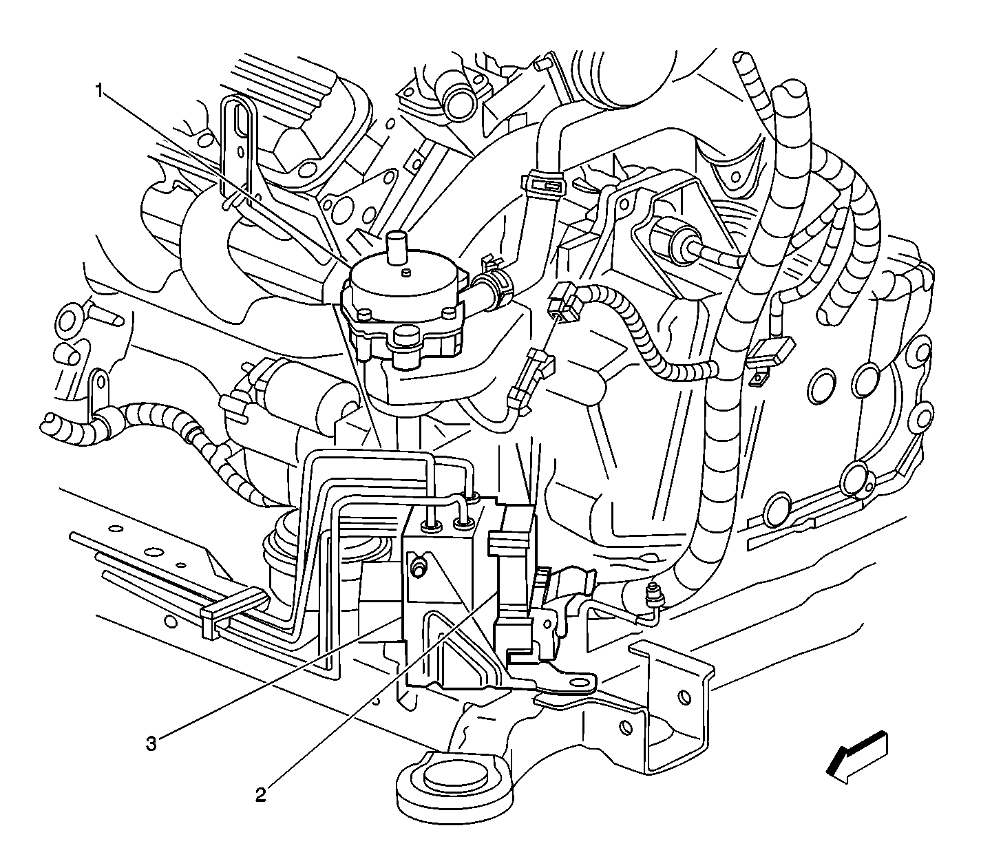

Object Number: 460289  Size: LF
(1)Secondary Air Injection (AIR) Pump Motor 1
(2)Electronic Brake Control Module (EBCM)
(3)Brake Pressure Modulator Valve (BPMV)
Figure 17:

Secondary Air Injection (AIR) Pump


Object Number: 833366  Size: LF
(1)Secondary Air Injection (AIR) Pump
Figure 18:

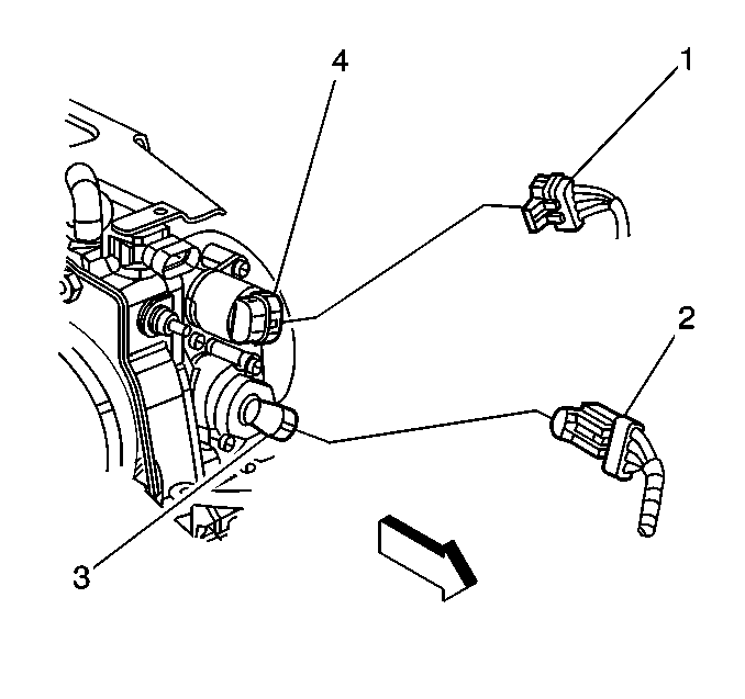
IAC Connector and TP Sensor


Object Number: 574138  Size: SH
(1)Idle Air Control (IAC) Valve Electrical Connector
(2)Throttle Position (TP) Sensor Electrical Connector
(3)Throttle Position (TP) Sensor
(4)Idle Air Control (IAC) Valve
Figure 19:

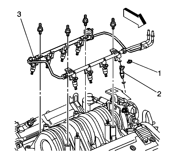
Fuel Rail Assembly


Object Number: 597227  Size: SH
(1)Fuel Injector Retaining Clip
(2)Fuel Injector
(3)Fuel Rail Assembly
Figure 20:

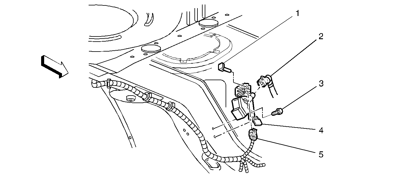
EVAP Vent Valve


Object Number: 342059  Size: SF
(1)Retainer
(2)Fresh Air Line
(3)Bolt
(4)Evaporative Emission (EVAP) Canister Vent Solenoid
(5)Evaporative Emission (EVAP) Canister Vent Solenoid Electrical Connector
Figure 21:

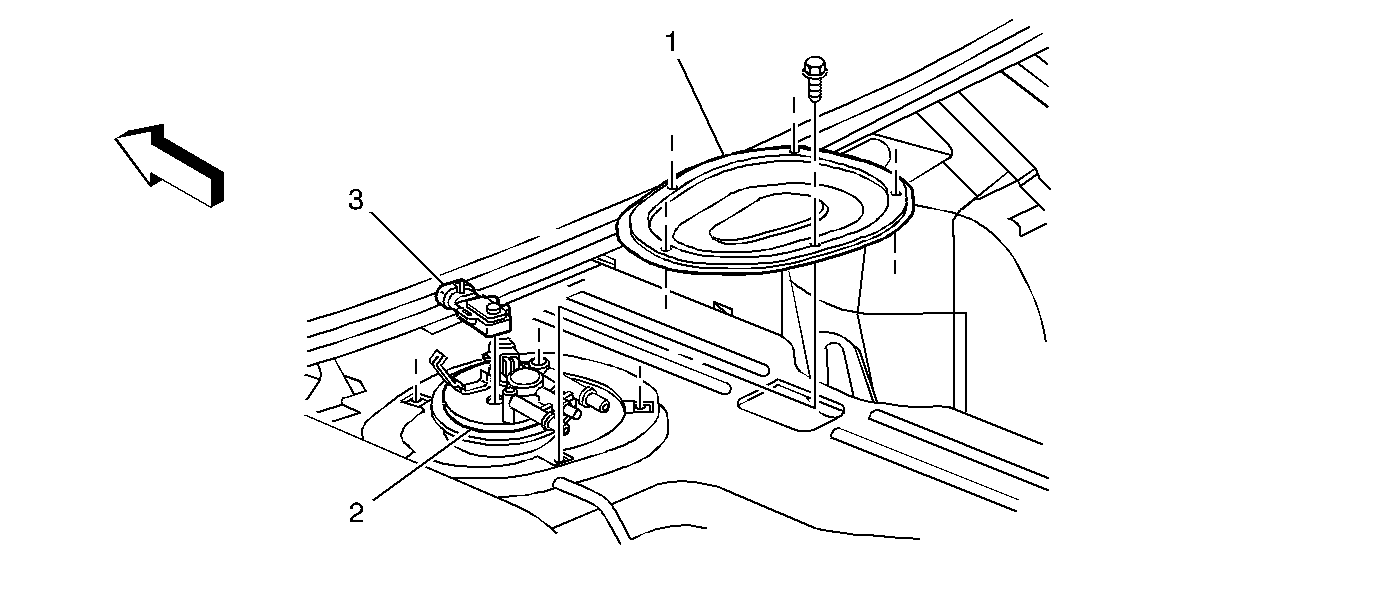
Fuel Tank Pressure Sensor


Object Number: 342178  Size: SF
(1)Fuel Sender Access Panel
(2)Fuel Pump and Sender Assembly
(3)Fuel Tank Pressure (FTP) Sensor