For 1990-2009 cars only
Removal Procedure
- Remove the left closeout/insulator. Refer to Instrument Panel Insulator Panel Replacement - Left Side in Instrument Panel, Gages, and Console.
- Remove the left knee bolster. Refer to Driver Knee Bolster Replacement in Instrument Panel, Gages, and Console.
- Remove the left front carpet retainer. Refer to Front Carpet Retainer Replacement in Interior Trim.
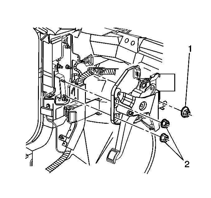
- Remove the park brake pedal assembly mounting nuts (1, 2).
- Position the park brake pedal assembly away from the mounting studs.
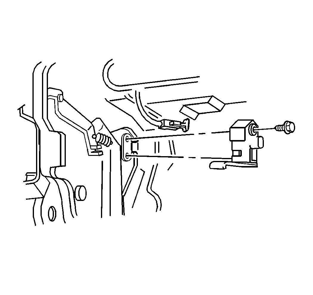
- Disconnect the electrical connector from the park brake warning lamp switch.
- Remove park brake warning lamp switch mounting bolt.
- Remove park brake warning lamp switch.


Installation Procedure
- Install the park brake warning lamp switch to the park brake lever assembly. Align the pin to the locator hole.
- Install the park brake warning lamp switch mounting bolt.
- Install the park brake pedal assembly to the mounting studs.
- Install the park brake pedal assembly mounting nuts (1, 2).
- Connect the electrical connector to the park brake warning lamp switch.
- Install the left knee bolster. Refer to Driver Knee Bolster Replacement in Instrument Panel, Gages, and Console.
- Install the left closeout/insulator. Refer to Instrument Panel Insulator Panel Replacement - Left Side in Instrument Panel, Gages, and Console.
- Install the left carpet retainer. Refer to Front Carpet Retainer Replacement in Interior Trim.

Notice: Refer to Fastener Notice in the Preface section.
Tighten
Tighten the park brake warning lamp switch mounting bolt to 2.0 N·m (18 lb in).

Tighten
Tighten the park brake pedal assembly mounting nuts to 24 N·m (18 lb ft).
