| Table 1: | A/C Compressor Clutch |
| Table 2: | A/C Compressor Clutch (V4U) |
| Table 3: | A/C Refrigerant Low Temperature Sensor |
| Table 4: | A/C Refrigerant Pressure Sensor |
| Table 5: | Air Temperature Actuator - Left |
| Table 6: | Air Temperature Actuator Assembly |
| Table 7: | Air Temperature Sensor - Auxiliary |
| Table 8: | Air Temperature Sensor - Inside |
| Table 9: | Air Temperature Sensor - Lower Left |
| Table 10: | Air Temperature Sensor - Lower Right |
| Table 11: | Air Temperature Sensor - Upper Left |
| Table 12: | Air Temperature Sensor - Upper Right |
| Table 13: | Ambient Air Temperature Sensor |
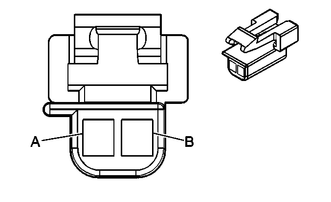
| Table 14: | Blower Motor |
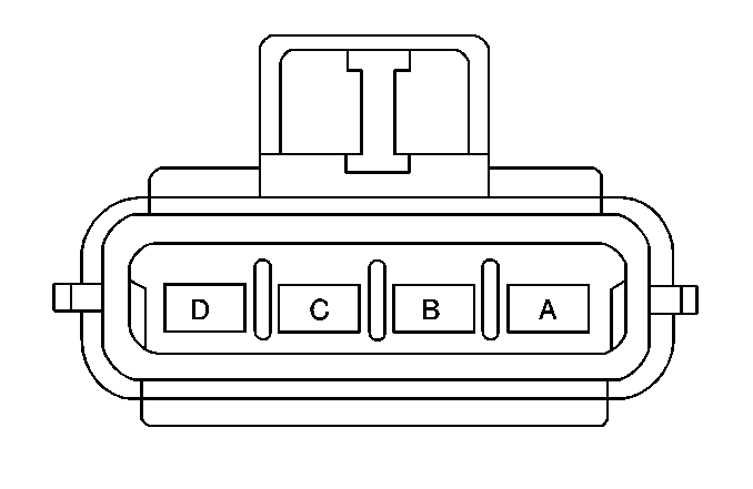
| Table 15: | Blower Motor - Auxiliary |
| Table 16: | Blower Motor Control Processor |
| Table 17: | Blower Motor Resistor Assembly - Auxiliary |
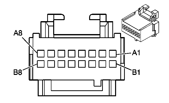
| Table 18: | HVAC Control Module - Auxiliary |
| Table 19: | Mode Actuator |
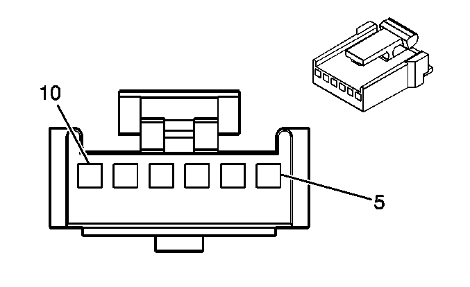
| Table 20: | Mode Actuator - Auxiliary |
| Table 21: | Recirculation Actuator |
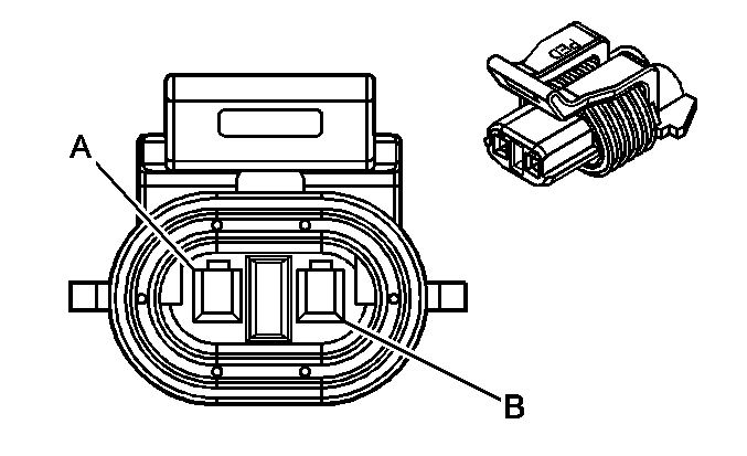
| |||||||
|---|---|---|---|---|---|---|---|
Connector Part Information |
| ||||||
Pin | Wire Color | Circuit No. | Function | ||||
A | DK GRN | 59 | A/C Compressor Clutch Supply Voltage | ||||
B | BLK/WHT | 1050 | Ground | ||||
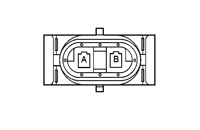
| |||||||
|---|---|---|---|---|---|---|---|
Connector Part Information |
| ||||||
Pin | Wire Color | Circuit No. | Function | ||||
A | BLK | 1550 | Ground | ||||
B | DK GRN | 59 | A/C Compressor Clutch Supply Voltage | ||||
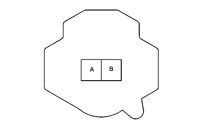
| |||||||
|---|---|---|---|---|---|---|---|
Connector Part Information |
| ||||||
Pin | Wire Color | Circuit No. | Function | ||||
A | BLK | 470 | A/C Refrigerant Low Temperature Sensor Signal | ||||
B | GRY | 731 | Low Reference | ||||
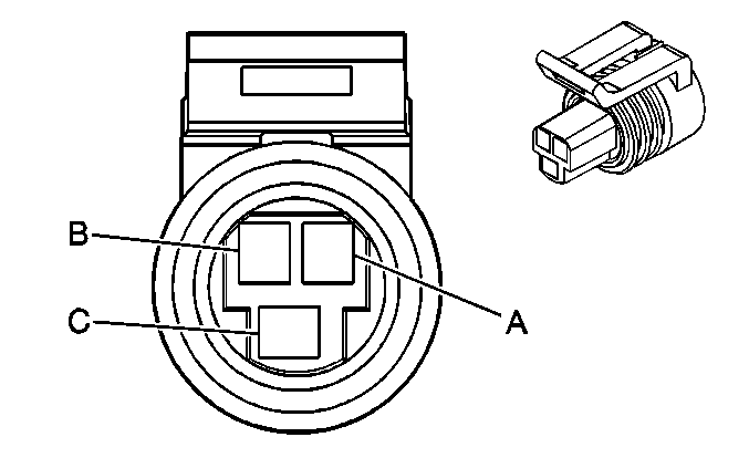
| |||||||
|---|---|---|---|---|---|---|---|
Connector Part Information |
| ||||||
Pin | Wire Color | Circuit No. | Function | ||||
A | BLK | 2751 | Low Reference | ||||
B | GRY | 2700 | 5 Volt Reference | ||||
C | RED/BLK | 380 | A/C Refrigerant Pressure Sensor Signal | ||||
| |||||||
|---|---|---|---|---|---|---|---|
Connector Part Information |
| ||||||
Pin | Wire Color | Circuit No. | Function | ||||
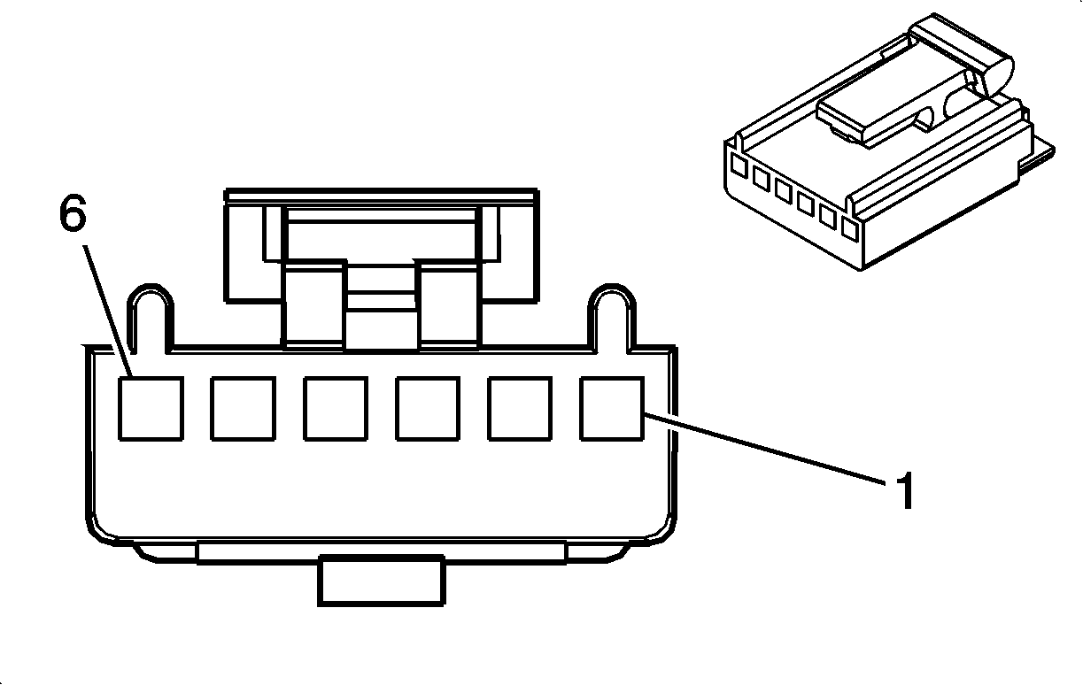
1 | YEL | 1791 | Left Air Temperature Door Control A | ||||
2 | DK BLU | 1199 | Left Air Temperature Door Control B | ||||
3-6 | -- | -- | Not Used | ||||

| |||||||
|---|---|---|---|---|---|---|---|
Connector Part Information |
| ||||||
Pin | Wire Color | Circuit No. | Function | ||||
1 | ORN | 2775 | Auxiliary Air Temperature Door Control B | ||||
2 | TAN | 2776 | Auxiliary Air Temperature Door Control A | ||||
3-4 | -- | -- | Not Used | ||||
5 | GRY/BLK | 2778 | Right Air Temperature Door Control A | ||||
6 | WHT/BLK | 1236 | Right Air Temperature Door Control B | ||||
| |||||||
|---|---|---|---|---|---|---|---|
Connector Part Information |
| ||||||
Pin | Wire Color | Circuit No. | Function | ||||
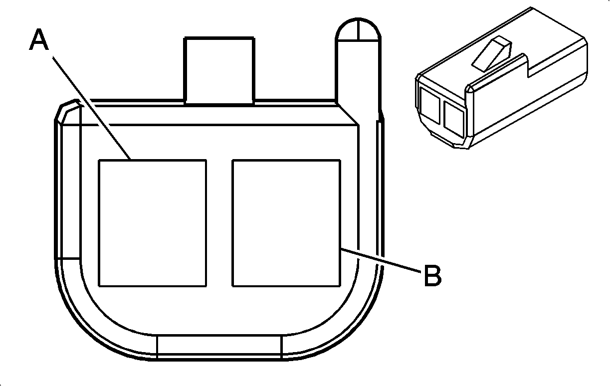
A | RED | 404 | Auxiliary Air Temperature Sensor Signal | ||||
B | YEL | 61 | Low Reference | ||||
| |||||||
|---|---|---|---|---|---|---|---|
Connector Part Information |
| ||||||
Pin | Wire Color | Circuit No. | Function | ||||
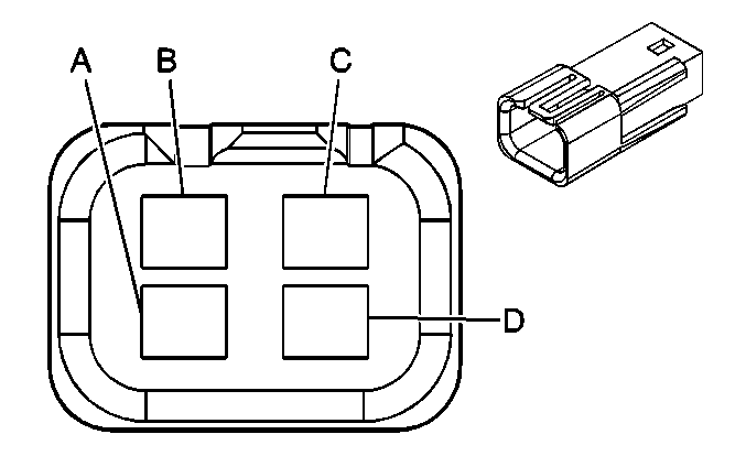
A | DK GRN | 734 | Inside Air Temperature Sensor Signal | ||||
B | BRN | 141 | Ignition 3 Voltage | ||||
C | BLK | 9999 | Inside Air Temperature Sensor Assembly Control | ||||
D | YEL | 61 | Low Reference | ||||

| |||||||
|---|---|---|---|---|---|---|---|
Connector Part Information |
| ||||||
Pin | Wire Color | Circuit No. | Function | ||||
A | BLK | 518 | Lower Left Air Temperature Sensor Signal | ||||
B | YEL/BLK | 61 | Low Reference | ||||

| |||||||
|---|---|---|---|---|---|---|---|
Connector Part Information |
| ||||||
Pin | Wire Color | Circuit No. | Function | ||||
A | BLK/WHT | 520 | Lower Right Air Temperature Sensor Signal | ||||
B | YEL/BLK | 61 | Low Reference | ||||

| |||||||
|---|---|---|---|---|---|---|---|
Connector Part Information |
| ||||||
Pin | Wire Color | Circuit No. | Function | ||||
A | BLK | 516 | Upper Left Air Temperature Sensor Signal | ||||
B | YEL | 61 | Low Reference | ||||

| |||||||
|---|---|---|---|---|---|---|---|
Connector Part Information |
| ||||||
Pin | Wire Color | Circuit No. | Function | ||||
A | TAN | 517 | Upper Right Air Temperature Sensor Signal | ||||
B | YEL | 61 | Low Reference | ||||
| |||||||
|---|---|---|---|---|---|---|---|
Connector Part Information |
| ||||||
Pin | Wire Color | Circuit No. | Function | ||||
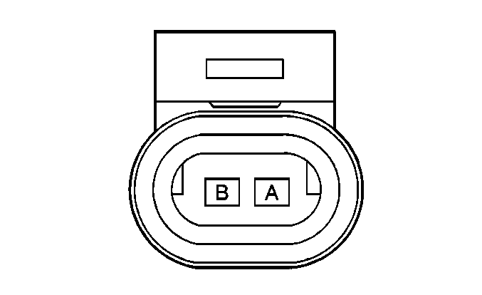
A | LT GRN/BLK | 735 | Ambient Air Temperature Sensor Signal | ||||
B | YEL | 61 | Low Reference | ||||

| |||||||
|---|---|---|---|---|---|---|---|
Connector Part Information |
| ||||||
Pin | Wire Color | Circuit No. | Function | ||||
A | BLK | -- | Blower Speed Control Output | ||||
B | PPL | -- | Blower Speed Control Ground | ||||
C | BARE | -- | Blower Motor Flange Ground | ||||
| |||||||
|---|---|---|---|---|---|---|---|
Connector Part Information |
| ||||||
Pin | Wire Color | Circuit No. | Function | ||||
A | ORN | 1440 | Battery Positive Voltage | ||||
B | BLK | 1052 | High Blower Motor Control | ||||
| |||||||
|---|---|---|---|---|---|---|---|
Connector Part Information |
| ||||||
Pin | Wire Color | Circuit No. | Function | ||||
A | BLK | 450 | Ground | ||||
B | RED | 1642 | Battery Positive Voltage | ||||
C | GRY/BLK | 754 | Blower Motor Speed Control | ||||
D | -- | -- | Not Used | ||||

| |||||||
|---|---|---|---|---|---|---|---|
Connector Part Information |
| ||||||
Pin | Wire Color | Circuit No. | Function | ||||
A | LT BLU | 72 | Medium 1 Blower Motor Control | ||||
B | PPL | 73 | Medium 2 Blower Motor Control | ||||
C | BLK | 1052 | High Blower Motor Control" Al | ||||
D | TAN | 63 | Low Blower Motor Control | ||||
| |||||||
|---|---|---|---|---|---|---|---|
Connector Part Information |
| ||||||
Pin | Wire Color | Circuit No. | Function | ||||
A1 | BLK | 450 | Ground (DTS) | ||||
A1 | BLK | 350 | Ground (DeVille, DHS) | ||||
A2 | PPL | 1807 | Class 2 Serial Data | ||||
A3 | GRY | 2502 | Auxiliary Mode Door Control | ||||
A4 | -- | -- | Not Used | ||||
A5 | BLK | 450 | Ground (DTS) | ||||
A5 | BLK | 350 | Ground (DeVille/DHS) | ||||
A6 | YEL | 1491 | Backlight Lamps Control | ||||
A7 | LT BLU | 72 | Medium 1 Blower Motor Control | ||||
A8 | TAN | 63 | Low Blower Motor Control | ||||
B1 | RED | 2503 | Low Reference | ||||
B2 - B3 | -- | -- | Not Used | ||||
B4 | PNK | 1593 | Auxiliary Mode Actuator Supply Voltage | ||||
B5 | BRN | 41 | Ignition 3 Voltage | ||||
B6 | ORN | 2840 | Battery Positive Voltage | ||||
B7 | ORN | 1052 | High Blower Motor Control | ||||
B8 | PPL | 73 | Medium 2 Blower Motor Control | ||||

| |||||||
|---|---|---|---|---|---|---|---|
Connector Part Information |
| ||||||
Pin | Wire Color | Circuit No. | Function | ||||
1 | YEL/BLK | 1814 | Mode Door Control A | ||||
2 | YEL | 1318 | Mode Door Control | ||||
3-6 | -- | -- | Not Used | ||||
| |||||||
|---|---|---|---|---|---|---|---|
Connector Part Information |
| ||||||
Pin | Wire Color | Circuit No. | Function | ||||
5-6 | -- | -- | Not Used | ||||
7 | GRY | 2503 | Low Reference | ||||
8 | PNK | 1593 | Auxiliary Mode Actuator Supply Voltage | ||||
9 | -- | -- | Not Used | ||||
10 | LT GRN | 2502 | Auxiliary Mode Door Control | ||||

| |||||||
|---|---|---|---|---|---|---|---|
Connector Part Information |
| ||||||
Pin | Wire Color | Circuit No. | Function | ||||
1 | PPL | 1838 | Recirculation Door Control A | ||||
2 | DK GRN | 1614 | Recirculation Door Control B | ||||
3-6 | -- | -- | Not Used | ||||
