Front Side Door Trim Panel Replacement Standard
Tools Required
J 36796 Clip Zip Clip
Removal Tool, or J 38778
Door
Trim Pad Clip Remover
Removal Procedure
- Position the window fully downward.
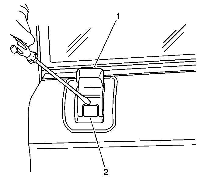
- Ensure the manual lock knob (1) is in the unlock position.
- Insert a flat bladed tool into the top service notch in order to disengage
the locking clip (2) located at the front of the manual lock knob (1).
- Remove the manual lock knob (1).
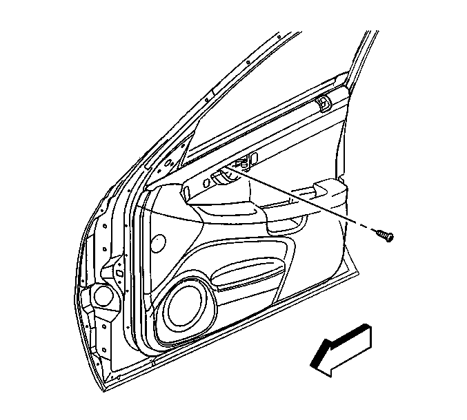
- Remove the inside handle bezel from the
inner door panel in the following order:
| 5.1. | Hold the inside handle to the open position. |
| 5.2. | Insert a flat bladed tool at the front lower corner of the bezel. |
| 5.3. | Pry outward on the bezel. |
| 5.4. | Remove the bezel from the inner door panel. |
- Remove the screw attaching the inside door handle to the sheet metal.
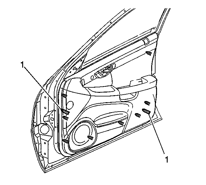
- Use the J 36796
or J 38778
in order to release the eight
retainers around the outside edges of the door trim panel.
Note the location
of the alignment datums (1).
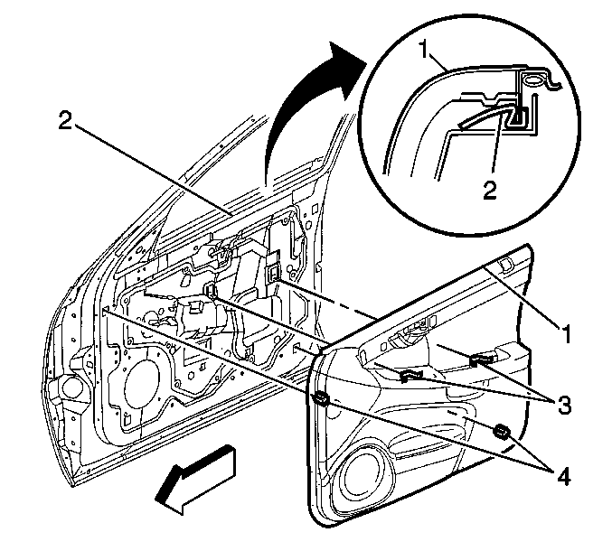
- Slide the door trim panel (1) upwards to release it from the following:
| • | The alignment datums (4) |
| • | The arm rest steel retainer clips (3) |
| • | The inner belt molding (2) |
- Disconnect the door trim panel electrical connector.
Installation Procedure
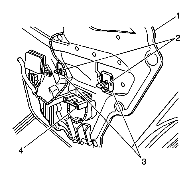
- Slide the electrical connector (4)
into position on the water deflector (1).
- Remove the steel retainer clips (2) from the arm rest pull handle
brackets.
- Slide the steel clips (2) into the nylon nuts (3).

- Install the door trim panel to the inner door in the following order:
| 4.1. | Position the door trim panel (1) downward over the following: |
| • | The inner belt molding (2) |
| 4.2. | Engage the door trim panel simultaneously into the following: |
| • | The alignment datums (4) |
| • | The electrical connector |
| • | The armrest pull handle retainer clips (3) |
Notice: Refer to Fastener Notice in the Preface section.
Caution: This screw must be properly installed. This screw is critical in order
to maintain retention of the inside handle to the slider-glide mechanism.
Failure to properly install this screw may allow the door to unlatch during
a collision, resulting in personal injury.

- Install the screw attaching the inside door handle to the sheet metal.
Tighten
Tighten the screw to 0.5 N·m (4 lb in).
- Install the inside handle bezel to the inner door panel in the following
order:
| 6.1. | Hold the inside handle to the open position. |
| 6.2. | Insert the rear hook on the bezel to the wood trim tab. |
| 6.3. | Press the forward end of the bezel inward until it is fully seated. |
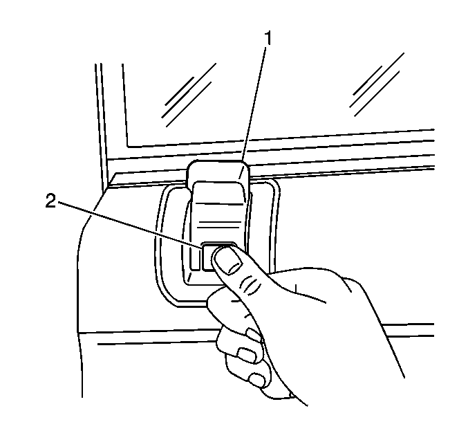
Important: Ensure the manual lock rod is in the full
up/unlocked position.
- Position the manual lock knob (1) into the bezel opening until the locking
clip (2) bottoms out on the bezel.
- Engage the locking clip (2) located at the front of the lock knob (1)
to the lock rod.


