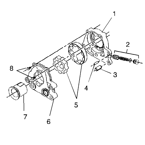
For 1990-2009 cars only
- Install the inner and the outer rotors (5) in the pump cover in the same orientation as removed. The outer rotor has one chamfered edge. The chamfered edge must be face-down (closest to the rear of the engine) in the pump body (1).
- Install the pressure relief valve piston, spring and retaining cap (2) in the pump housing bore.
- Install the pressure relief valve cap retaining pin (4).
- Pack the pump housing with white petroleum jelly to ensure pump priming.
- Assemble the housing and cover over the locating dowel (3).
- Insert a 9.5 mm (0.375 in) drill in the pump mounting hole on the opposite side in order to aid in the alignment of the housing and cover.
- Install the oil pump cover bolts (8).

Notice: Use the correct fastener in the correct location. Replacement fasteners must be the correct part number for that application. Fasteners requiring replacement or fasteners requiring the use of thread locking compound or sealant are identified in the service procedure. Do not use paints, lubricants, or corrosion inhibitors on fasteners or fastener joint surfaces unless specified. These coatings affect fastener torque and joint clamping force and may damage the fastener. Use the correct tightening sequence and specifications when installing fasteners in order to avoid damage to parts and systems.
Tighten
Tighten the oil pump cover bolts to 12 N·m (106 lb in).
